7 overcurrent protection, 8 open loop protection, 7 overtemperature protection – Cirrus Logic CS1616A User Manual
Page 11: 1 internal overtemperature protection, 2 external overtemperature protection
CS1615A/16A
DS1033PP2
11
5.6.7 Overcurrent Protection
Overcurrent protection (OCP) is implemented by monitoring the
voltage across the sense resistor. If this voltage exceeds a
threshold V
OCP(th)
of 1.69V, a fault condition occurs. The IC
output is disabled and the controller attempts to restart after
approximately one second.
5.6.8 Open Loop Protection
Open loop protection (OLP) and sense resistor short protection
are implemented by monitoring the voltage across the resistor. If
the voltage on pin FBSENSE does not reach the protection
threshold V
OLP(th)
of 200mV, the IC output is disabled, and the
controller attempts to restart after approximately one second.
5.7 Overtemperature Protection
The CS1615A/16A incorporates internal overtemperature
protection (iOTP) and the ability to connect an external
overtemperature sense circuit for IC protection. Typically, an
NTC thermistor is used.
5.7.1 Internal Overtemperature Protection
Internal overtemperature protection (iOTP) is activated, and
switching is disabled when the die temperature of the devices
exceeds 135°C. There is a hysteresis of about 14°C before
resuming normal operation.
5.7.2 External Overtemperature Protection
The external overtemperature protection (eOTP) pin is used to
implement overtemperature protection. A negative temperature
coefficient (NTC) thermistor resistive network is connected to pin
eOTP, usually in the form of a series combination of a resistor R
S
and a thermistor R
NTC
(see Figure 15). The CS1615A/16A
cyclically samples the resistance connected to pin eOTP.
The total resistance on the eOTP pin gives an indication of the
temperature and is used in a digital feedback loop to adjust
current I
CONNECT
into the NTC and series resistor R
S
to maintain
a constant reference voltage V
CONNECT(th)
of 1.25V. Current
I
CONNECT
is generated from a controlled current source with a
full-scale current of 80
A. When the loop is in equilibrium, the
voltage on the eOTP pin fluctuates around V
CONNECT(th)
. A
resistance ADC is used to generate I
CONNECT
. The ADC output
is filtered to suppress noise and compared against a reference
that corresponds to 125°C. A second low-pass filter with a time
constant of two seconds filters the ADC output and is used to
scale down the internal dim level of the system (and hence LED
current I
LED
) if the temperature exceeds 95°C. The large time
constant for this filter ensures that the dim scaling does not
happen spontaneously and is not noticeable (suppress spurious
glitches). The eOTP tracking circuit is designed to function
accurately with external capacitance up to 470pF.
The tracking range of this resistance ADC is approximately
15.5k
to 4M. The series resistor R
S
is used to adjust the
resistance of the NTC to fall within the ADC tracking range,
allowing the entire dynamic range of the ADC to be well used.
The CS1615A/16A recognizes a resistance (R
S
+R
NTC
) equal to
20.3k
which corresponds to a temperature of 95°C, as the
beginning of an overtemperature dimming event and starts
reducing the power dissipation. The output current is scaled until
the series resistance (R
S
+R
NTC
) value reaches 16.6k
(125°C).
Beyond this temperature, the IC shuts down until the resistance
(R
S
+R
NTC
) rises above 19.23k
. This is not a latched protection
state, and the ADC keeps tracking the temperature in this state
in order to clear the fault state once the temperature drops below
110°C.
When exiting reset, the chip enters startup and the ADC quickly
(<5ms) tracks the external temperature to check if it is below the
110°C reference code before the controller is powered up. If this
check fails, the chip will wait until this condition becomes true
before initializing the rest of the system.
For example, a 14k
(±1% tolerance) series resistor is required
to allow measurements of up to 130°C to be within the eOTP
tracking range when a 100k
NTC with a Beta of 4275. If the
temperature exceeds 95°C, thermistor R
NTC
is approximately
6.3k
and series resistor R
S
is 14k
, so the eOTP pin has a total
resistance of 20.3k
. The eOTP pin initiates protective dimming
action by reducing the power dissipation. At 125°C the thermistor
R
NTC
has 2.6k
plus a series resistor R
S
equal to 14k
present
a resistance of 16.6k
at the eOTP pin reaching the point where
a thermal shutdown fault intervenes. The CS1615A/16A will
continue to monitor pin eOTP and once the series resistor R
S
plus the thermistor R
NTC
rises above 19.23k
the device will
resume power conversion (see Figure 16).
If the external overtemperature protection feature is not required,
connect the eOTP pin to GND using a 50k
-to-500k resistor to
disable the eOTP feature.
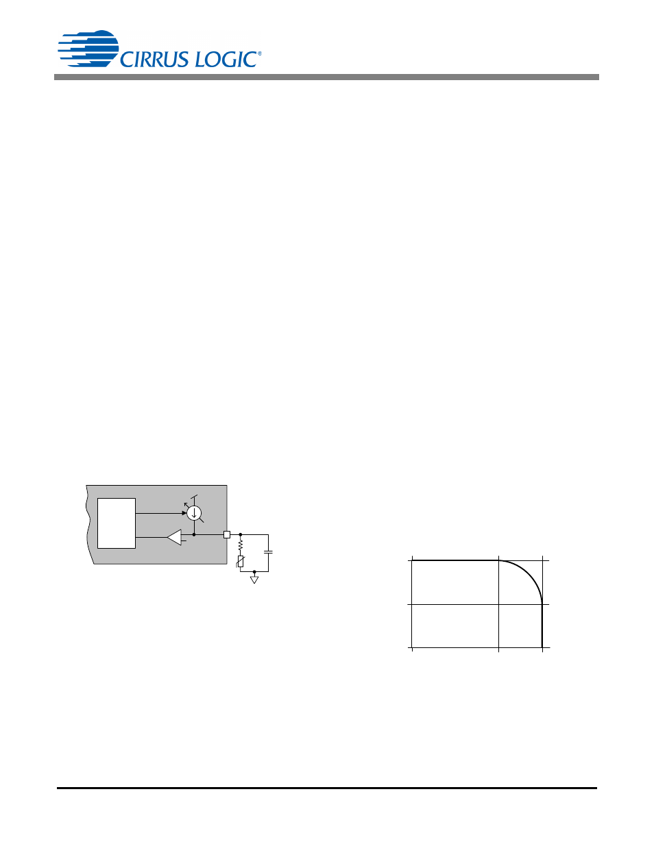
CS1615A/16A
+
-
I
CONNE CT
V
CONNE CT
(th)
Comp_Out
eOTP
Control
eOTP
R
S
C
NTC
NTC
V
DD
10
(Optional )
Figure 15. eOTP Functional Diagram
Temperature (°C)
Cu
rr
e
n
t
(I
LE
D
, N
o
m
.)
125
95
50%
100%
0
25
Figure 16. eOTP Temperature vs. Impedance