0 operation, 0 specifications, 0 introduction – Young Barometric Pressure Sensor Model 61302L User Manual
Page 2: 0 installation
4.0 OPERATION
Operation begins approximately 1 second after power is
applied. Output will appear after a delay determined by
the number of samples averaged and the output rate. With
default values (1.8 Hz output and 10 samples averaged),
output begins after an initial 5 second delay then remains
continuous at the 1.8 Hz rate. Parameters for output rate
and number of samples averaged may be changed using
software commands.
4.1 CURRENT OUTPUT
Calibrated 4-20 mA current output is always active. The
connection scheme appears in the Appendix A Wiring
Diagram.
The current output scale may be mapped to any part of the
500 to 1100 hPa pressure range using the IOUT HI and
IOUT LO software parameters. The standard setting maps
4 to 20 mA with 500 to 1100 hPa. With this setting:
hPa = 37.5 * mA + 350
Effective resolution is about 0.15 hPa
Greater effective resolution may be achieved by mapping
the current output to a narrower range of pressure with the
IOUT HI and IOUT LO parameters. For example, with IOUT
LO set to 950 hPa and IOUT HI set to 1050 hPa:
hPa = 6.25 * mA + 925
Effective resolution is about 0.025 hPa
Please see section 4.3 below for details on changing the
IOUT HI and LO parameters.
4.2 SERIAL OUTPUT
The 61302L may be confi gured for either full-duplex RS-232
or half-duplex RS-485 serial communication. For RS-232
serial communication, both jumpers at P3 must be in position
‘2’. For RS-485 serial communication, both jumpers at P3
must be in position ‘4’. Jumper location details appear in the
Appendix A Wiring Diagram.
Standard baud rate is 9600 but any of several available baud
rates between 1200 and 38400 may be used.
Jumpers at P1 and software parameter settings determine
serial output format.
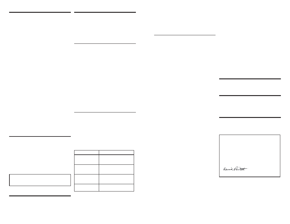
Format
Description
Continuous ASCII
Text
(standard)
9600 baud
10 sample average
1.8 Hz output
Polled ASCII Text
9600 baud
10 sample average
Output when polled
Marine NMEA
4800 baud
10 sample average
1 Hz output
Software
Output parameters determined
by software settings
See Appendix A Wiring Diagram for details on jumper P1
configuration options and serial output examples.
1.0 SPECIFICATIONS
Pressure
500 to 1100 hPa standard range
Digital Accuracy*
0.2 hPa (25°C)
0.3 hPa (-40°C to +60°C)
Analog Accuracy**
0.05% of analog pressure range
Analog Temperature
Dependence**
0.0017% of analog pressure range
per °C (25°C reference)
Long Term Stability: 0.2% FS per year
* Defi ned as ±1 standard deviation from NIST-traceable
pressure reference in clean, dry air. Includes non-linearity,
hysteresis, repeatability, and calibration uncertainty.
** Defi ned as ±1 standard deviation from ideal analog output.
Total analog output accuracy is the root sum square of
digital accuracy, analog accuracy, and analog temperature
dependence.
Output Rate
1.8 Hz (max) to 1 per minute
Current Output
4 to 20 mA
12-bit resolution (1 in 4000) Selectable
pressure range: 500 to 1100 hPa
(standard)
Serial Output
Full-duplex RS-232
Half-duplex
RS-485
1200 to 38400 baud
Continuous
ASCII
text
Polled
ASCII
text
NMEA
0.01 hPa resolution
Supply Voltage
7 to 30 VDC
25 mA max in 4-20 mA mode
7 mA with serial I/O only
Case Fiber-reinforced
thermoplastic
Weight
44 g (1.5 oz)
2.0 INTRODUCTION
MODEL 61302L Barometric Pressure Sensor is a versatile
electronic barometer featuring high accuracy, low power,
wide operating temperature range, and calibrated 4-20 mA
output, and RS-232/485 serial data I/O.
The 4-20 mA output and RS-485 serial I/O make the
61302L ideal for commercial and industrial applications
that commonly use these signals.
Full scale current output may be set to span any portion of
the 500 to 1100 hPa operating range. Serial output options
include continuous or polled ASCII text output or NMEA
marine output. The sensor is supplied with the following
standard configuration:
Current Output 4-20 mA = 500 to 1100 hPa
RS-232 Continous ASCII text output
10 samples averaged
1.8 Hz update rate
3.0 INSTALLATION
The sensor operates over a temperature range of -40°C to
+60°C and must remain dry. Electrical connections are made
with the 5-position terminal plug included with the sensor.
Jumper settings may be used to select operating options.
Access jumpers by loosening two screws in the sensor
enclosure and removing the cover. See Appendix A for wiring
details and jumper settings.
In POLLED ASCII mode, the unit sends data only after
receiving a poll command. The poll command is Ma! where
‘a’ is the address value. The standard address is ‘0’ (ASCII
48) for a poll command of M0! Please see section 4.3 for
details on changing the poll address.
Upon receiving a properly addressed poll command, the
unit immediately sends data.
4.3 SOFTWARE COMMANDS
Software commands sent via serial communication may
be used to set operational parameters. The sensor must
be configured for serial communication and connected
to a PC or other compatible device using a program like
HyperTerm.
New settings are stored in temporary memory and
must be burned to flash with command CMD420 to be
retained.
Note that the P1 jumper must be configured for
SOFTWARE format to change baud rate, sample average
count, and output rate parameters.
Although the sensor may receive commands at any
time, measurement output may be paused by sending
three ESC (ASCII 27) characters or CMD300 1. While
paused, COMMAND mode is indicated by a “>” prompt.
All commands must be terminated with a carriage return
CR (ASCII 13).
Use “?” to list available commands as shown below.
> ?
Y O U N G 6 1 3 0 2 L S E R I E S B A R O M E T E R V 2 . 0 2
- - - - - - - - - - - - - - - - - - - - - - - - - - - - - - - - - - - - - - - -
C M D 1 0 0 n O U T P U T P E R I O D ( 0 - 6 0 s e c )
C M D 1 0 5 n A V G S A M P L E C O U N T ( 0 - 3 2 )
C M D 1 1 0 n O U T P U T F O R M A T
( 1 = A S C I I 2 = P O L L E D 3 = N M E A 4 - R A W 5 - D I A G )
C M D 1 2 0 n M U L T I P L I E R ( 1 0 0 0 0 = 1 . 0 0 0 0 )
C M D 1 2 5 n O F F S E T ( h P A x 1 0 0 )
C M D 1 3 0 n S E A L E V E L C O R R E C T I O N ( h P A x 1 0 0 )
C M D 1 4 0 n I O U T R A N G E H I ( 5 0 0 - 1 1 0 0 )
C M D 1 4 2 n I O U T R A N G E L O ( 5 0 0 - 1 1 0 0 )
C M D 1 5 0 c P O L L A D D R C H A R
C M D 1 6 0 n B A U D R A T E ( 3 8 4 0 0 , 9 6 0 0 , 4 8 0 0 , 2 4 0 0 , 1 2 0 0 )
C M D 3 0 0 n 1 = S T O P , 2 = R U N
C M D 3 1 0 n F O R C E I O U T ( 0 - 2 0 0 0 0 F U L L S C A L E )
C M D 4 0 0 n 1 = R P T T E X T , 2 = R P T C O D E O N L Y
C M D 4 1 0 G E T C A L T A B L E
C M D 4 2 0 S T O R E S E T U P P A R A M E T E R S
>
CMD100 n sets output period in seconds. When set to
zero, the output rate is 1.8 per second.
CMD105 n sets the average sample count. Higher sample
count yields more stable readings but will lengthen
the startup delay.
CMD110 n sets output format.
CMD120 n sets the output multiplier. 10000 represents
1.0000
CMD125 n sets the output offset in hPa x 100
CMD130 n sets the sea level correction in hPa x 100
=[
P
unadjust
*(
Mult / 10000
)]
+
[(
Offset
/
100
)
+
(
Correction
Sea Lvl
/
100
)]
CMD140 n sets the IOUT Pressure Range HI
CMD142 n sets the IOUT Pressure Range LO
IOUT Pressure Range HI must be greater than IOUT
Pressure Range LO
CMD150 c sets the poll address character. Any ASCII
character from ‘0’ (ASCII 48) to ‘z’ (ASCII 122) may
be used.
CMD160 n sets the baud rate. Acceptable values are
38400, 9600, 4800, 2400, and 1200. Note that the
baud rate change occurs immediately after the
command is received. Therefore, in order to continue
communicating, the serial communication program
that issued the command must also change to
match.
CMD300 n causes the sensor to pause or resume
measurement. 1 = Stop, 2 = Run.
CMD400 n causes the sensor to issue a report
summarizing parameter settings.
1 = Text (parameter values and labels)
2 = Code Only (parameter values only).
CMD420 burns the current parameter settings to flash
memory. This step must take place to retain
changes to settings otherwise parameters will revert
to previous values at the next power up.
5.0 MAINTENANCE
The MODEL 61302L barometer requires no regular
maintenance. Periodic calibration certification, if
required, is available from the factory.
6.0 WARRANTY
This product is warranted to be free of defects in
materials and construction for a period of 12 months
from date of initial purchase. Liability is limited to repair
or replacement of defective item. A copy of the warranty
policy may be obtained from R. M. Young Company.
7.0 CE COMPLIANCE
This product complies with European CE requirements for
the EMC Directive. Please note that shielded cable must
be used.
Declaration of Conformity
R.M. Young Company
2801 Aero Park Drive
Traverse City, Mi 49686 USA
Model 61302L Barometric Pressure Sensor
The undersigned hereby declares, on behalf of R.M. Young
Company the the above-referenced product, to which this
declaration relates, is in conformity with the provisions of:
Council Directive 2004/108/EC (December 15, 2004) on
Electromagnetic
Compatibility;
David
Poinsett
R & D Manager