Introduction, Initial checkout, Installation – Young Gill Propeller Anemometer Models 27106DT User Manual
Page 2: Calibration, Gill propeller anemometer
Page 1
INTRODUCTION
The Gill Propeller Anemometer Photochopper is a low threshold
precision air velocity sensor employing a fast response helicoid
propeller. The instrument uses a high quality optical photo chopper
which converts propeller rotation to a square wave signal whose
frequency is linearly proportional to air velocity. The output signal is
the same regardless of propeller rotation. For applications where
propeller rotation in two directions is required, the model 27106F is
offered.
Airflow from any direction may be measured, however, the
propeller responds only to the component of the air flow which is
parallel to the axis of its rotation. Off-axis response closely
approximates a cosine curve (see accompanying graphs) with
appropriate polarity. With perpendicular air flow the propeller does
not rotate.
The instrument mounts to 3/4 inch standard pipe. A rugged cable
connector provides both electrical and mechanical connection. A
dust cap is provided to protect the connector when the instrument
is removed.
INITIAL CHECKOUT
When the instrument is unpacked it should be carefully checked for
any signs of shipping damage. The propeller shaft should rotate
easily without friction.
Using the WIRING DIAGRAM as a guide, connect the instrument to
an oscilloscope or frequency meter and check for proper signals
from the sensor. The calibration may be checked using the methods
outlined in the CALIBRATION section of this manual.
INSTALLATION
Generally, the instrument should be oriented with the propeller
facing the predominant flow of air being measured. In some cases
it is appropriate to orient the instrument so the predominant air flow
is perpendicular to the propeller such as in applications measuring
the vertical component of wind. Keep in mind that off-axis
response increases the effective threshold and distance constant.
For vertical measurements mount the instrument so the propeller
faces upward. This helps prevent moisture or dirt from entering
around the propeller hub and potentially contaminating the
bearings.
If the instrument is used to measure high air velocity or left for
extended periods without attention, tape the threaded cable
connector collar to eliminate the possibility of loosening from
vibration. The threaded joint between the photochopper and shaft
housings may also be taped.
CALIBRATION
Calibration is determined by propeller pitch and the output
frequency of the photo chopper transducer.
The Model 08254 Carbon Fiber Thermoplastic Propeller has a 30
cm/rev pitch. This is equivalent to 0.00500 m/s per rpm and is
accurate to ±1%. Zero offset is insignificant. Formulas for other
units of measurement appear below.
Information on checking bearing and transducer torque, which can
affect propeller threshold, also appear in the MAINTENANCE
section.
SPECIFICATION SUMMARY
Range:
0 to 35 m/s (80 mph)
Sensor:
20 cm diameter 4-blade helicoid
propeller molded of carbon fiber
thermoplastic
Pitch:
30.0 cm air passage per revolution
Distance Constant:
2.1 m (6.9 ft.) for 63% recovery
Threshold Sensitivity:
0.4 m/s (0.8 mph)
Transducer:
Optical photochopper
Power Requirement:
10-14 VDC (12mA @ 12 VDC)
Operating Temp:
-50 to 50°C (-58 to 122°F)
Transducer Output:
Square wave signal with pulse
amplitude approximately equal to
supply voltage -2.
Output Frequency:
10 pulses per propeller revolution
(0.030 m/s per Hz)
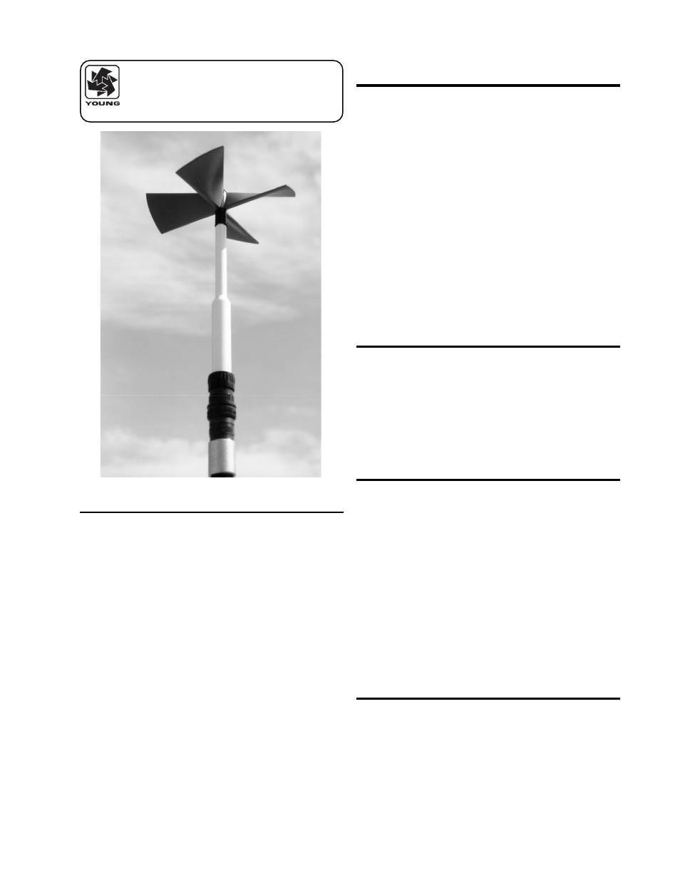
MODEL 27106DT
GILL PROPELLER
ANEMOMETER