Gill propeller anemometer introduction, Initial checkout, Installation – Young Gill Propeller Anemometer Models 27106T User Manual
Page 2
Page 1
27106T-90
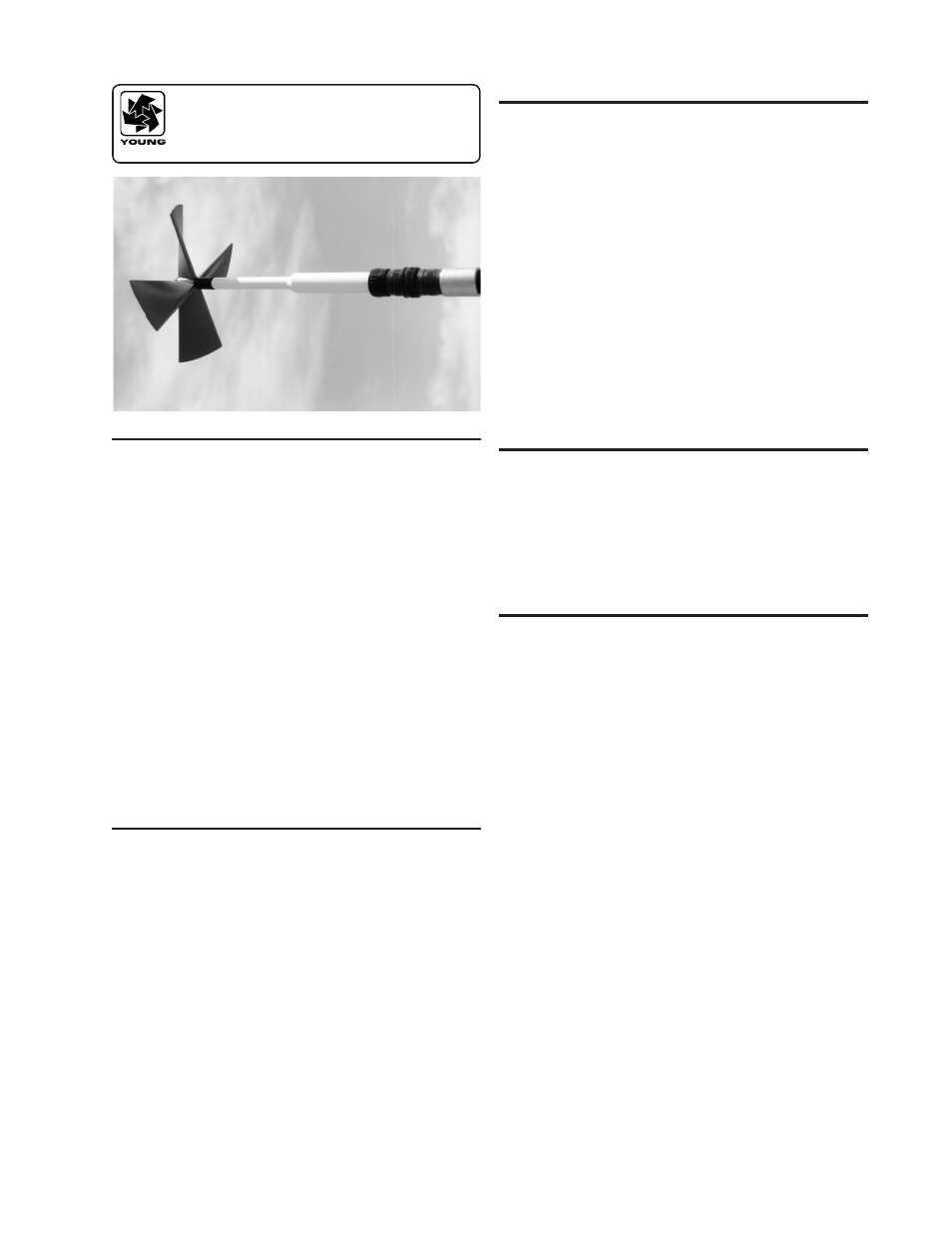
MODEL 27106T
GILL PROPELLER
ANEMOMETER
INTRODUCTION
The Gill Propeller Anemometer is a low threshold precision air
velocity sensor employing a fast response helicoid propeller.
The instrument uses a high quality tech-generator transducer
which converts propeller rotation to a DC voltage that is linearly
proportional to air velocity. The output signal is suitable for a wide
range of signal translators and data logging devices.
Airflow from any direction may be measured, however, the propeller
responds only to the component of the air flow which is parallel to
the axis of its rotation. Off-axis response closely approximates a
cosine curve (see accompanying graphs) with appropriate polarity.
With perpendicular air flow, the propeller does not rotate.
For detailed studies of low air speeds, optional propeller shaft
extensions improve response in the 90° stall region by improving
symmetry and reducing the stall angle.
The instrument mounts to 3/4 inch standard pipe. A rugged cable
connector provides both electrical and mechanical connection. A
dustcap is provided to protect the connector when the instrument
is removed.
INITIAL CHECKOUT
When the instrument is unpacked it should be carefully checked
for any signs of shipping damage. The propeller shaft should rotate
easily without friction.
Using the WIRING DIAGRAM as a guide, connect the instrument
to an indicator or voltmeter and check for proper signals from
the sensor. The calibration may be checked using the methods
outlined in the CALIBRATION section of this manual.
INSTALLATION
Generally, the instrument should be oriented with the propeller
facing the predominant flow of air being measured. In some cases
it is appropriate to orient the instrument so the predominant air flow
is perpendicular to the propeller such as in applications measuring
the vertical component of wind. Keep in mind that off-axis response
increases the effective threshold and distance constant.
For vertical measurements mount the instrument so the propeller
faces upward. This helps prevent moisture or dirt from entering
around the propeller hub and potentially contaminating the
bearings.
If the instrument is used to measure high air velocity or left for
extended periods without attention, tape the threaded cable
connector collar to eliminate the possibility of loosening from
vibration. The threaded joint between the generator and shaft
housings may also be taped.
For some applications commutator ripple from the tech-generator
may need to be reduced. Use a 500 uF 10 VDC non-polarized
capacitor connected across the sensor leads as shown in the wiring
diagram. Given the low internal resistance of the tech-generator
the effective time constant of this filter is approximately 15 mS and
will not degrade measurement accuracy to any significant degree.
The instrument measures both forward and reverse air flow. Signal
polarity relative to the connection pins is shown in the wiring
diagram. In applications measuring horizontal air flow, most users
connect the sensor to produce a positive signal with flow from
the front (counterclockwise propeller rotation). In applications
measuring vertical air flow, the sensor is usually connected so
downdrafts produce a negative signal, updrafts a positive signal.
Output from the tech-generator should be connected to a load
impedance of 10k ohms or higher.
SPECIFICATION SUMMARY
Range, Axial Flow
0-40 m/s (90 mph)
Range, All Angles
0-35 m/s (80 mph)
Propeller
20 cm diameter 4-blade helicoid propeller
molded of carbon fiber thermoplastic
Pitch
30.0 cm air passage per revolution
Distance Constant*
2.1 m (6.9 ft.)
Threshold Sensitivity* 0.4 m/s (0.8 mph)
Signal Output
Analog DC voltage proportional to axial
wind component. Polarity reverses with
reverse rotation.
1800 rpm (500 mV) = 9.0 m/s (20.1 mph).
Power Requirement
Anemometer is self powered.
Specifications represent nominal values determined in accordance
with ASTM standard procedures.
*
Threshold and Distance Constant values are for axial flow.
GENERAL
Operating Temperature: -50 to 50°C (-58 to 122°F)