Introduction, Initial check-out, Installation – Young Wind Monitor Model 05103V User Manual
Page 2
Page 1
05103V-90(H)
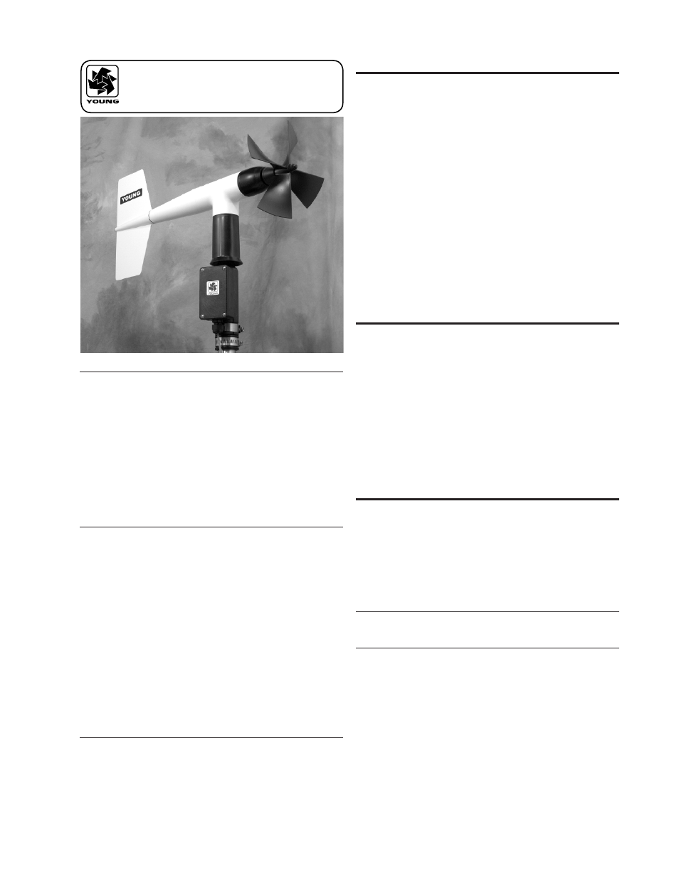
MODEL 05103V
WIND MONITOR
with VOLTAGE OUTPUTS
INTRODUCTION
The Wind Monitor measures horizontal wind speed and direction.
It is rugged and corrosion resistant, yet accurate and lightweight.
The housing, nose cone, propeller, and other components are
injection molded U.V. stabilized plastic. Both the propeller and
vertical shafts use stainless steel precision grade ball bearings.
Propeller rotation produces an AC sine wave signal with frequency
proportional to wind speed. Internal circuitry converts the raw
signal to a linear voltage output.
Vane position is sensed by a 10K ohm precision conductive plastic
potentiometer. This signal is also converted to voltage output.
The instrument mounts directly on standard one inch pipe, outside
diameter 34 mm (1.34"). An orientation ring is provided so the
instrument can be removed for maintenance and re-installed
without loss of wind direction reference. Both the sensor and the
orientation ring are secured to the mounting pipe by stainless steel
band clamps. Electrical connections are made in a junction box at
the base.
INITIAL CHECK-OUT
When the Wind Monitor is unpacked it should be checked carefully
for any signs of shipping damage.
Remove the plastic nut on the propeller shaft. Install the propeller
on the shaft with the serial number of the propeller facing forward
(into the wind). The instrument is aligned, balanced and fully
calibrated before shipment; however, it should be checked both
mechanically and electrically before installation. The vane and
propeller should easily rotate 360° without friction. Check vane
balance by holding the instrument base so the vane surface
is horizontal. It should have near neutral torque without any
particular tendency to rotate. A slight imbalance will not degrade
performance.
INSTALLATION
Proper placement of the instrument is very important. Eddies from
trees, buildings, or other structures can greatly influence wind
speed and wind direction observations. To get meaningful data for
most applications, locate the instrument well above or upwind from
obstructions. As a general rule, the air flow around a structure is
disturbed to twice the height of the structure upwind, six times the
height downwind, and up to twice the height of the structure above
ground. For some applications it may not be practical or necessary
to meet these requirements.
FAILURE TO PROPERLY GROUND THE WIND MONITOR
MAY RESULT IN ERRONEOUS SIGNALS
OR TRANSDUCER DAMAGE.
Grounding the Wind Monitor is vitally important. Without proper
grounding, static electrical charge can build up during certain
atmospheric conditions and discharge through the transducers.
This discharge may cause erroneous signals or transducer failure.
To direct the discharge away from the transducers, the mounting
post assembly in which the transducers are mounted is made with
a special anti-static plastic. It is important that the mounting post
be connected to a good earth ground. There are two ways this
may be accomplished. First, the Wind Monitor may be mounted
on a metal pipe which is connected to earth ground. The mounting
pipe should not be painted where the Wind Monitor is mounted.
Towers or masts set in concrete should be connected to one or
more grounding rods. If it is difficult to ground the mounting post
in this manner, the following method should be used. Inside
the junction box the terminal labeled EARTH GND is internally
WIND SPEED SPECIFICATION SUMMARY
Range
0 to 100 m/s (224 mph)
Sensor
18 cm diameter 4-blade helicoid
polypropylene propeller, 29.4 cm air
passage per revolution
Distance Constant
2.7 m (8.9 ft.) for 63% recovery
Threshold Sensitivity 1.0 m/s (2.2 mph)
Transducer
Centrally mounted stationary coil,
2K Ohm nominal DC resistance
Output Signal
50 mV per M/S
WIND DIRECTION (AZIMUTH) SPECIFICATION SUMMARY
Range
360° mechanical, 355° electrical (5° open)
Sensor
Balanced vane, 38 cm (15 in) turning
radius.
Damping Ratio
0.3
Delay Distance
1.3 m (4.3 ft) for 50% recovery
Threshold Sensitivity 1.1 m/s (2.4 mph) at 10° displacement
Damped Natural
Wavelength
7.4 m (24.3 ft)
Undamped Natural
Wavelength
7.2 m (23.6 ft)
Transducer
Precision conductive plastic potentiometer,
10K ohm resistance (±20%),
0.25% linearity, life expectancy 50 million
revolutions, rated 1 watt at 40°C,
0 watts at 125°C
Output Signal
13.9 mV per degree
GENERAL
Power Requirement:
8 - 24 VDC (5mA @ 12 VDC)
Operating Temperature:
-50 to 50°C (-58 to 122°F)