Wind monitor-ma introduction, Initial checkout – Young Marine Wind Monitor Model 05106 User Manual
Page 2
Page 1
05106-90(J)
MODEL 05106
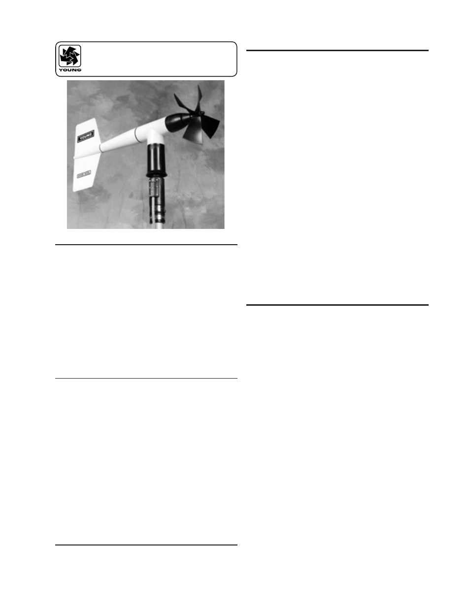
WIND MONITOR-MA
INTRODUCTION
The Wind Monitor-MA measures horizontal wind speed and
direction. Originally developed for ocean data buoy use, it is rugged
and corrosion resistant yet accurate and light weight. The main
housing, nose cone, propeller, and other internal parts are injection
molded U.V. stabilized plastic. Both the propeller and vertical
shafts use stainless steel precision grade ball bearings. Bearings
have light contacting teflon seals and are filled with a low torque
wide temperature range grease to help exclude contamination and
moisture.
Propeller rotation produces an AC sine wave signal with frequency
proportional to wind speed. This AC signal is induced in a
stationary coil by a six pole magnet mounted on the propeller shaft.
Three complete sine wave cycles are produced for each propeller
revolution.
Vane position is transmitted by a 10K ohm precision conductive
plastic potentiometer which requires a regulated excitation voltage.
With a constant voltage applied to the potentiometer, the output
signal is an analog voltage directly proportional to azimuth angle.
The instrument mounts on standard one inch pipe, outside
diameter 34 mm (1.34"). An orientation ring is provided so the
instrument can be removed for maintenance and reinstalled without
loss of wind direction reference. Both mounting post assembly and
orientation ring are secured to the mounting pipe by stainless steel
band clamps. A 3 meter (9.8 ft) pigtail cable assembly is supplied
for electrical connections. For longer cable lengths a user supplied
junction box or connector may be used. A variety of devices are
available for signal conditioning, display, and recording of wind
speed and direction.
INITIAL CHECKOUT
When the Wind Monitor-MA is unpacked it should be checked
carefully for any signs of shipping damage. Remove the plastic
nut on the propeller shaft. Install the propeller on the shaft so
the letter markings on the propeller face forward (into the wind).
Engage the propeller into the molded ribs on the propeller shaft
hub. The instrument is aligned, balanced and fully calibrated before
shipment, however it should be checked both mechanically and
electrically before installation. The vane and propeller should easily
rotate 360° without friction. Check vane balance by holding the
instrument base so the vane surface is horizontal. It should have
near neutral torque without any particular tendency to rotate. A
slight imbalance will not degrade performance.
The potentiometer requires a stable DC excitation voltage. Do
not exceed 15 volts. When the potentiometer wiper is in the 5°
deadband region, the output signal is "floating" and may show
varying or unpredictable values. To prevent false readings, signal
conditioning electronics should clamp the signal to excitation
or reference level when this occurs.
NOTE: Young signal
conditioning devices clamp the signal to excitation level.
Avoid a short circuit between the azimuth signal line and either the
excitation or reference lines. Although there is a 1K ohm current
limiting resistor in series with the wiper for protection, damage to
the potentiometer may occur if a short circuit condition exists.
Before installation, connect the instrument to an indicator as shown
in the wiring diagram and check for proper wind speed and azimuth
values. Position the vane over a sheet of paper with 30° or 45°
crossmarkings to check vane alignment. To check wind speed,
temporarily remove the propeller and connect the shaft to an
Anemometer Drive. Details appear in the CALIBRATION section of
this manual.
WIND SPEED SPECIFICATION SUMMARY
:
Range
0 to 100 m/s (224 mph)
Sensor
18 cm diameter 4-blade helicoid propeller
molded of polypropylene
Pitch
29.4 cm air passage per revolution
Distance Constant
2.7 m (8.9 ft.) for 63% recovery
Threshold Sensitivity 1.1 m/s (2.4 mph)
Transducer
Centrally mounted stationary coil,
2K 0hm nominal DC resistance
Transducer Output
AC sine wave signal induced by rotating
magnet on propeller shaft. 80 mV p-p at
100 rpm. 8.0 V p-p at 10,000 rpm.
Output Frequency
3 cycles per propeller revolution
(0.098 m/s per Hz)
WIND DIRECTION (AZIMUTH) SPECIFICATION SUMMARY:
Range
360° mechanical, 355° electrical (5° open)
Sensor
Balanced vane, 38 cm (15 in) turning radius.
Damping Ratio
0.25
Delay Distance
1.3 m (4.3 ft) for 50% recovery
Threshold Sensitivity
1.1 m/s (2.4 mph) at 10° displacement
Damped Natural
Wavelength
7.4 m (24.3 ft)
Undamped Natural
Wavelength
7.2 m (23.6 ft)
Transducer
Precision conductive plastic potentiometer, 10K
ohm resistance (±20%), 0.25% linearity, life
expectancy 50 million revolutions, rated 1 watt
at 40° C, 0 watts at 125° C
Transducer Excitation
Requirement
Regulated DC voltage, 15 VDC max
Transducer Output
Analog DC voltage proportional to azimuth angle
with regulated excitation voltage applied across
potentiometer.
GENERAL:
Operating Temp:
-50 to 50°C (-58 to 122°F)