0 specification summary, 0 introduction, 0 initial checkout – Young Ultrasonic Anemometer Model 81000VRE User Manual
Page 2: Ultrasonic anemometer
Page 1
81000VRE-90
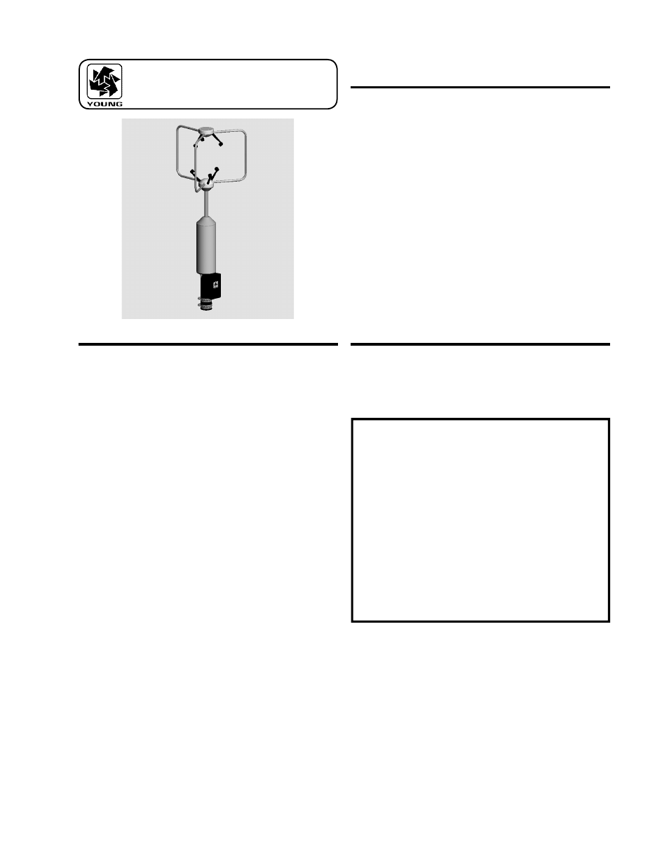
MODEL 81000VRE
ULTRASONIC ANEMOMETER
1.0 SPECIFICATION SUMMARY
WIND SPEED
Range:
0
to
40
m/s
(0
to
90
mph)
Resolution:
0.01
m/s
Threshold:
0.01
m/s
Accuracy:
±1%
rms
±0.05
m/s
(0
to
30
m/s)
±3%
rms
(30
to
40
m/s)
WIND DIRECTION
Azimuth
Range:
0.0
to
359.9
degrees
Elevation
Range:
±60.0
degrees
Resolution:
0.1
degree
Accuracy:
±2°
(1
to
30
m/s)
±5°
(30
to
40
m/s)
SPEED OF SOUND
Range:
300
to
360
m/s
Resolution:
0.01
m/s
Accuracy:
±0.1%
rms
±0.05
m/s
(0
to
30
m/s
wind)
SONIC TEMPERATURE
Range:
-50
to
+50
ºC
Resolution:
0.01
ºC
Accuracy:
±
2
ºC
(0
to
30
m/s
wind)
VOLTAGE INPUT (4 CHANNELS)
Range:
0
to
5000mV
V1
and
V2
0
to
1000mV
V3
and
V4
Resolution:
1
part
in
4000
Accuracy:
±
0.1%
of
full
scale
GENERAL
Air sample column:
10 cm high X 10 cm diameter
Air
sample
path:
15
cm
Output
rate:
4
to
32
Hz
(selectable)
Output
formats:
Serial
data
(selectable)
RS-232
and
RS-485
Baud
Rates:
1200
to
38400
Power Supply:
12 to 24 VDC, 110 mA
Dimensions:
Overall
height
70
cm
Support
arm
radius
17
cm
Mounting
34
mm
(1.34
in)
diameter
(standard
1
inch
pipe)
Weight:
Sensor
weight
1.7
kg
(3.8
lb)
2.0 INTRODUCTION
The Young Model 81000VRE measures three dimensional wind
velocity and speed of sound based on the transit time of ultrasonic
acoustic signals. Sonic temperature is derived from speed of
sound which is corrected for crosswind effects. Four voltage input
channels measure DC signals from external sensors concurrent
with wind measurements
Measurement data are available as serial output using RS-232 or
RS-485 connections. A variety of serial output formats are avail-
able including a custom format which is easily set by the user.
Operating parameters may be edited via simpli ed menus using
an ordinary serial communication program like HyperTerm. All
parameters are stored in non-volatile memory.
Superior environmental resistance is achieved by using UV stabi-
lized thermoplastic, stainless steel, and anodized aluminum com-
ponents. Electrical connections are made via an easily accessible
junction box. The unit mounts on standard 1 inch pipe, outside
diameter 34mm (1.34").
3.0 INITIAL CHECKOUT
Carefully unpack the unit and inspect for physical damage. Any
damage should be reported to the shipper. The sensor arrives fully
calibrated and ready to use.
FACTORY
DEFAULT
CONFIGURATION:
Serial Outputs:
-
RS232
at
38400
Baud
- ASCII Text Serial String
Wind
Speed
-
3D
(m/s)
Direction
(Deg)
Elevation
(Deg)
Speed
of
Sound
(m/s)
Sonic
Temperature
(°C)
Analog
Voltage
Inputs:
- Channel V1:
0-5000mV Full Scale
- Channel V2: 0-5000mV Full Scale
-
- Channel V3:
0-1000mV Full Scale
- Channel V4:
0-1000mV Full Scale
NOTE: Factory default settings omit voltage input
measurements from the serial output string. To in-
clude them, set CUSTOM or POLL CUSTOM serial
output format. See section 6.7. All analog input mea-
surements are normalized to a 0-4000 unitless scale
.
A simple four-step operational check may be performed as follows:
1. Remove junction box cover. Connect power and signal wires
to terminals as indicated in wiring diagram (APPENDIX A) for
RS-232 OUTPUT. Connect serial cable to computer COM
port.
2. Start a serial communications program (like HyperTerm) with
baud rate at 38400 and ow control set to NONE.
3. Apply power to the 81000VRE sensor. There will be a 4
second delay for initialization then the unit will begin to output
data at four times per second using the following format: speed
(m/s) azimuth (deg) elevation (deg) speed-of-sound (m/s)
sonic-temperature (°C). Verify that all values are present on