Commissioning, operation – WIKA A2G-60 User Manual
Page 10
WIKA operating instructions air2guide model A2G-60
GB
10
40202798.02 08/2012 GB/D/F/E/I
6. Commissioning, operation
Electrical connection
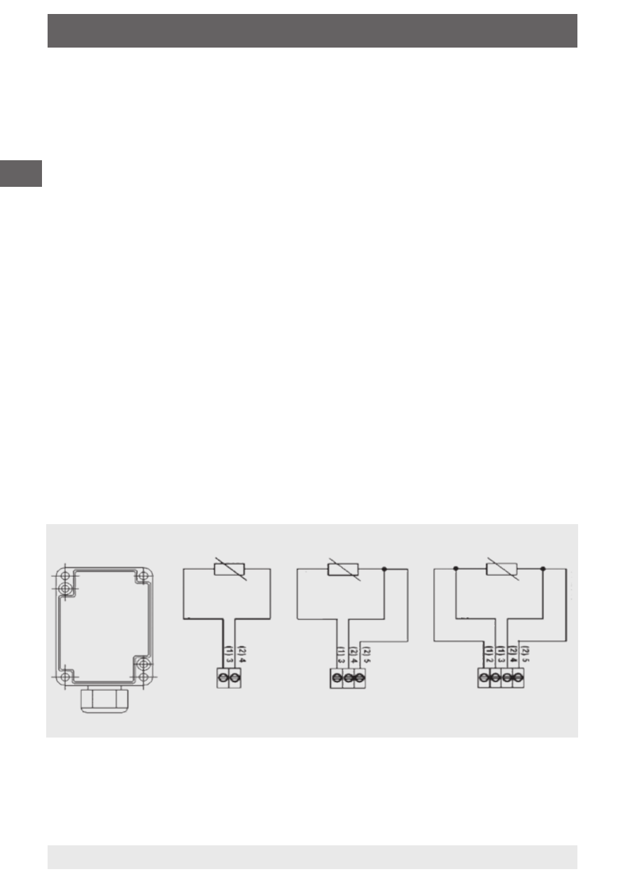
Connection diagram (selection) Pt1000/Ni1000 sensor
The instruments are designed to operate with safety extra-low voltage
(SELV). When wiring up the instruments, the technical specifications for
those instruments should be followed. Particularly for passive sensors,
e.g. Pt1000, etc., in a 2-wire configuration, the sensor lead resistance
should be taken into account. If necessary, this must be corrected in the
connected electronics. Through self-heating, the measurement current
affects the measuring accuracy and should, therefore, not be above
1 mA.
In the case of a sensor with transmitter, as a rule, the transmitter should
be operated in the middle of the measuring range, since deviations can
occur at the range limits.
The ambient temperature of the transmitter electronics should be kept
constant. The transmitters must be operated with a constant power
supply.
The measuring range is altered by changing the positions of the jumper
links (see connection diagram). The initial value of the new measuring
range is then available after approx. 2 s.
Sensor
Sensor
Sensor
2-wire
3-wire
4-wire
white
br
own
gr
een
red
white
br
own
white
white
red