Instruction manual ni-205, Weatherproof explosionproof – WIKA APA10 User Manual
Page 6
INSTRUCTION MANUAL
NI-205
Rev. 1 12/02
ETTORE CELLA SPA Viale de Gasperi, 48 - Casella Postale (P.O. Box) 96 - I 20010 Bareggio (MILANO) ITALY
Telefoni +39 029036.1146/7 - 029036.1237/41 - FAX +39 029036.1331 Email: [email protected]
11. STOPPING AND DISMOUNTING
Before proceeding with these operations ensure that
the plant or machines have been put into the
conditions foreseen to allow these operations.
With reference to figures 8 and 9
Remove the power supply (signal) from the electrical
line. Close the root valve (6) and open the drain.
Remove the plug (2), open the valve (3) and wait until
the process fluid has drained from the tubing through
the drain.
Do not dispose of the process fluid into the environment,
if this can cause pollution or damage to people.
Unscrew the three-piece joint (8).
CAUTION: do not open the cover of explosionproof
pressure switches (Series APA) when energized, in
explosive atmospheres.
Unscrew the three-piece joint (10) (electrical cable
tubing).
Remove the instrument cover and disconnect the
electrical cables from the terminal block and earth
screws. Remove the screws fixing the case to the panel
(or pipe) and remove the instrument, taking care to slide
the electrical conductors out from the case.
Replace the instrument cover. Insulate and protect the
conductors remaining on the plant. Temporarily plug the
tubing (4).
In case of explosionproof instruments (Series APA) it is
recommended to follow - at least – the standard EN-
60079-17 for the withdrawal from service of electrical
apparatus.
12. DEMOLITION
The instruments are mainly made of stainless steel and
aluminium and therefore, once the electrical parts have
been dismounted and the parts coming into contact with
fluids which could be harmful to people or the
environment have been properly dealt with, they can be
scrapped.
WEATHERPROOF EXPLOSIONPROOF
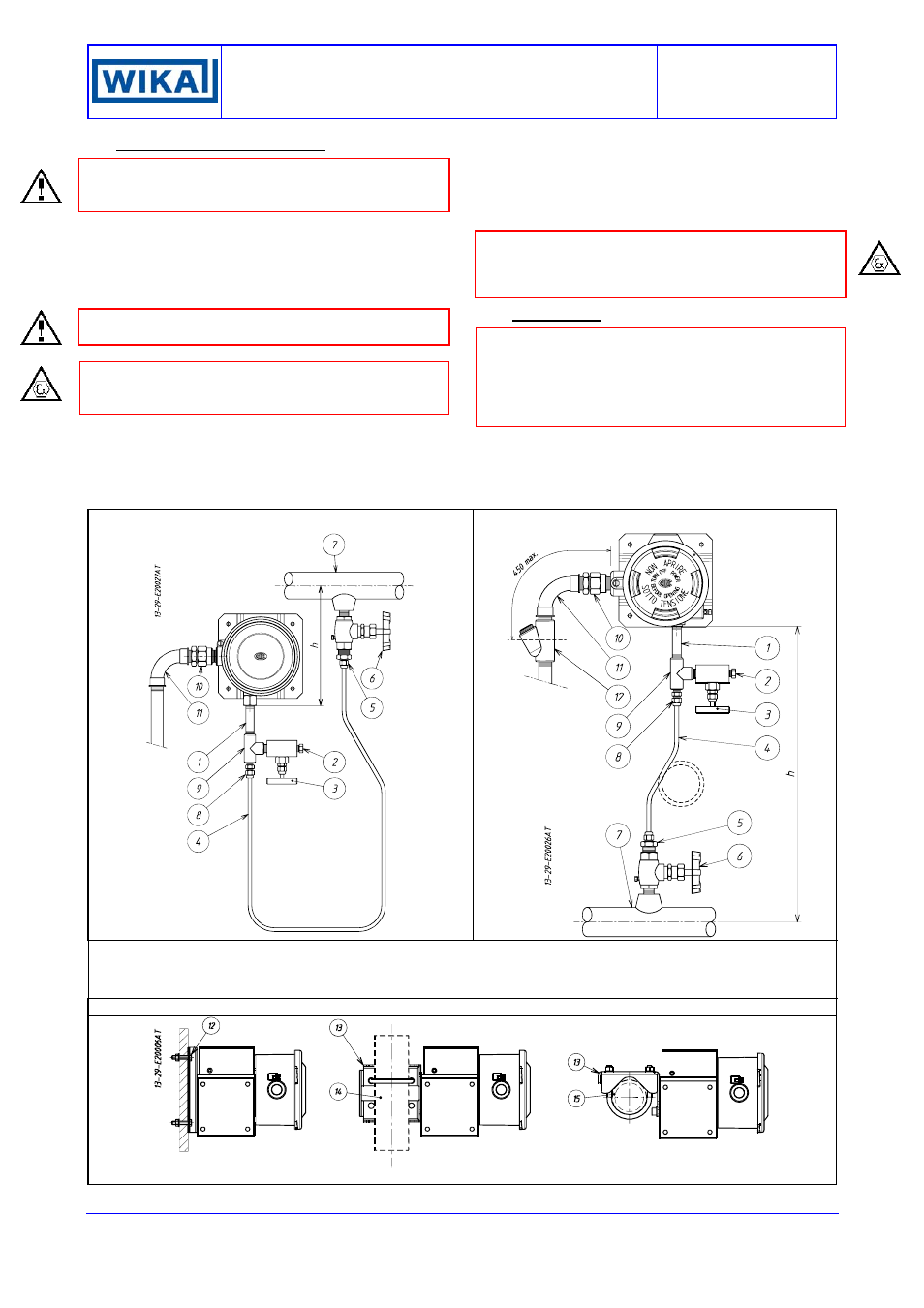
Fig. 8 -
Example of connections -
Fig. 9 -
Example of connections -
1 – Fitting
2 - Drain plug
3 - Service valve
4 - Piping
5 - Three piece fitting
6 - Root valve with drain
7 - Process piping
8 - Three piece fitting
9 - “T” fitting
10 - Three piece fitting
11 - Curve
12 - Blocking joint
13 - M6 screws (No. 4)
14 - Bracket for 2” pipe
15 - Vertical pipe
16 - Horizontal pipe
Fig. 10 -
Example of mounting
Montaggio a parete
Montaggio su staffa per tubo da 2”
Surface mounting
2” pipe mounting