Instruction manual ni-205e – WIKA APA10 User Manual
Page 2
INSTRUCTION MANUAL
NI-205E
Rev. 1 12/02
1. GENERAL
NOTES
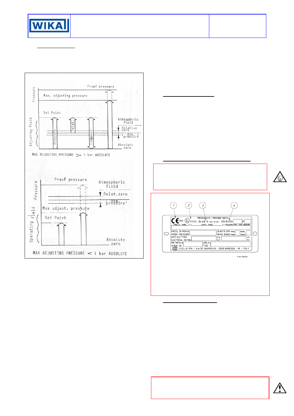
1.1 FOREWORD
APW and APA series were designed for applications
where absolute-zero rather than atmospheric set point
value is required (see fig.1)
Fig. 1 -
Pressure designation
1.2 RANGE CHOICE
The wrong choice of a series or a model, as well as the
incorrect installation, lead to malfunction and reduce
instrument life. Failure to abide by the indications given
in this manual can cause damage to the instrument, the
environment and persons.
1.3 ALLOWED OVERRANGE
Pressure exceeding the working range can be
occasionally tolerated provided they remain within the
limits stated in the instrument features (vacuum or proof
pressure). Continuous pressures exceeding the
working range can be applied to the instrument provided
they are clearly stated in the instrument features. The
current and voltage values stated in the technical
specifications and ratings must not be exceeded.
Transitory overranges can have a destructive effect on
the switch.
1.4 MECHANICAL VIBRATIONS
Can generally lead to the wearing of some parts of the
instrument or cause false actuation. It is therefore
recommended that the instrument be installed in a place
where there are no vibrations. In cases where this is
impossible it is a good idea to take measures to lessen
the effects (elastic supports, installation with the peg of
the microswitch positioned at right angles to the
vibration plane, etc.).
1.5 TEMPERATURE
Due to the temperature of both the environment and the
process fluid, the temperature of the instrument could
exceed the allowed limits (normally from -20° to +70°C).
Therefore, in case it does, suitable measures (protection
against heat radiation, fluid separators, cooling coils,
heated lockers) must be taken. Process fluid or its solid
particles must not however go inside instrument
chambers.
2. OPERATING
PRINCIPLE
The process pressure, acting on the diaphragm
sensitive element, that has got absolute vacuum as
reference pressure, determines its elastic deformation
which is used to activate one or two electric
microswitches regulated at set point values. The
microswitches are of the rapid release type with
automatic rearm. When the pressure moves away from
the set values, returning towards the normal values, the
switch is rearmed. The differential gap (difference
between the set point value and the reset value) can be
set or adjustable (letter R in the contact codes).
3. IDENTIFICATION PLATE AND MARKINGS
The instrument is fitted with a metal plate bearing all its
functional characteristics and – in case of
explosionproof execution (Series APA) – also the
markings prescribed by standard CEI EN 50014. Fig. 2
shows the plate mounted on explosionproof instruments.
Fig. 2 -
Explosionproof instruments plate
1
CE marking and identification number of the notified body
responsible for production surveillance.
2 Apparatus classification according to ATEX 94/9 CE
directive.
3
Type of protection and ambient temperature limits of
operation.
4
Notified body that issued the type certificate and number of
said certificate.
4. SET POINT REGULATION
Each microswitch is independent and can be regulated
by means of a screw (for adjustment) in such a way that
it is released when the pressure reaches (increasing or
decreasing) the desired value (set point).
The instrument is usually supplied with the switches set
at the setting range value nearest to zero (factory
calibration). The instrument is supplied with an
adhesive rating plate showing the set point calibration
value. With factory calibration the values are not
indicated on the ratings as these are temporary and will
be modified with the definitive values. Prior to
installation the instrument must be calibrated and the
definitive calibration values written on the adhesive
rating plate using a suitable indelible ink pen.
If the instrument has been ordered with a specific
calibration, it is a good rule to check the calibration
values marked on the relevant adhesive label, prior to
installation.