Instruction manual ni-205e – WIKA APA10 User Manual
Page 3
INSTRUCTION MANUAL
NI-205E
Rev. 1 12/02
The position of the adjustment screws is given in figure
The effect that the direction of rotation of the
adjustment screws has is described on the adhesive
plate.
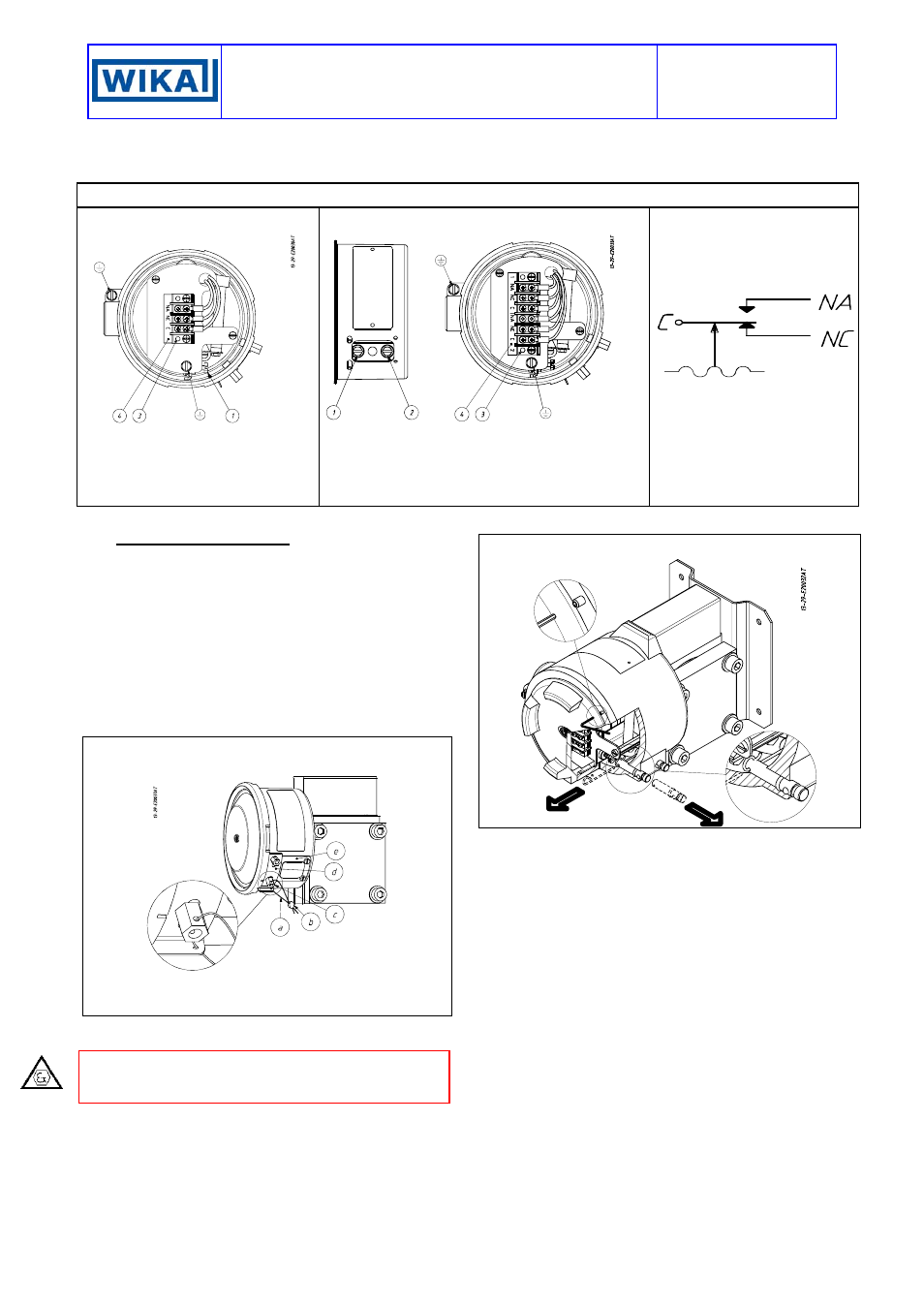
Fig. 3 -
Electrical connections and adjustment screws
One contact instruments
Two contact instruments
Microswitch electrical circuit
State of the contacts at
atmospheric pressure
1 - Microswitch set point calibration
screws
3 - Terminal block
4 - Electrical connection identification
plate
1 - Microswitch 2 set point calibration screws
2 - Microswitch 1 set point calibration screws
3 - Terminal block
4 - Electrical connection identification plate
Designation of the contacts:
C - common
NA - Normally open
NC - Normally closed
5. SET POINT CALIBRATION
In order to proceed with the calibration and the
periodical functional verification of the instrument a
suitable calibration circuit (fig. 6) and an adequate
pressure source is required.
5.1 PRELIMINARY OPERATIONS
Weatherproof pressure switches (Series APW) (Fig.
4)
Remove the blocking device fixed to the side of the
instrument case and the adjustment screw access plate.
Remove the cover by rotating it in an anticlockwise
direction.
Fig. 4 -
Weatherproof pressure switch blocking and plumbing
device
a - Plumbing wire
b - Plumbing
c - Blocking nut
d - Blocking bracket
e - Adjustment screw access
plate
Explosionproof pressure switches (Series APA)
(Fig.5)
CAUTION: do not open the cover of explosionproof
pressure switches (Series APA) when energized, in
explosive atmospheres.
Loosen the locking headless screw situated on the
cover using a 1,5 hexagonal key then unscrew the
cover. Remove the internal blocking device inserted on
the closure plugs and slide out the plugs.
Fig. 5 -
Explosionproof pressure switch blocking device
5.2 CALIBRATION CIRCUIT AND OPERATIONS
Prepare the control circuit as indicated in Fig.5.
The warning lamps should be connected to contact 1 or
2 in the NO or NC position according to the required
contact action.
Connection of C and NO terminals
•••• If the circuit is open at the working pressure, the switch
closes the circuit as the pressure increases when the
desired value is reached.
• If the circuit is closed at the working pressure, the
switch opens the circuit as the pressure decreases
when the desired value is reached.
Connection of C and NC terminals
• If the circuit is closed at the working pressure, the
switch opens the circuit as the pressure increases
when the desired value is reached.
• If the circuit is open at the working pressure, the switch
closes the circuit as the pressure decreases when the
desired value is reached.
The test instrument should have a measurement range
approximately equal to or slightly wider than the
pressure switch range and should have an accuracy
consistent with the precision required to calibrate the set
point.