Instruction manual ni-205 – WIKA APA10 User Manual
Page 5
INSTRUCTION MANUAL
NI-205
Rev. 1 12/02
6.4
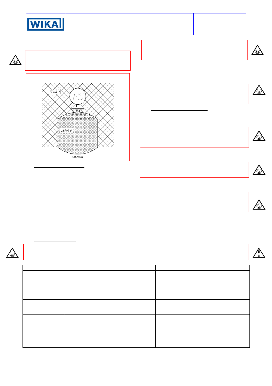
SPECIAL NOTE FOR INSTALLATION OF
CATEGORY 1 / 2 G PRESSURE SWITCHES
Explosionproof pressure switches (Series APA) can be
installed on processes requiring apparatus of group II
category 1 in an ambient requiring apparatus of group II
category 2 (see Fig. 7).
Fig. 7 -
Installation of Group II Cat. 1 / 2 G instruments
7. INSTRUMENT
PLUMBING
Weatherproof pressure switches (Series APW)
The plumbing, aimed as a guarantee against possible
tampering of the calibration and electrical connections,
can be carried out using a flexible steel wire (a) inserted
into the holes in the screw (c) and the bracket (d)
provided for this purpose (see Fig. 4).
Explosionproof pressure switches (Series APA)
Plumbing is not necessary as the cover is blocked with a
headless screw, the closure plugs of the adjustment
screw access holes are blocked by means of the
internal blocking device and the instrument does not
have to be opened when installed (see Fig. 5).
8. PUTTING INTO OPERATION
As the signal transmitted by the instrument is used in a
complex system, it is necessary that the means of
putting it into operation are established by those in
charge of the plant.
The instrument comes into operation as soon as the root
valve is opened. Any possible drainage of the
connection tubing can be carried out by removing the
safety plug and opening the service valve with the
necessary caution.
In case of explosionproof instruments (Series APA),
initial inspections are to be carried out according to
customer procedures and at least in accordance with
Standard EN-60079-17.
9. FUNCTIONAL
VERIFICATION
This will be carried out according to the Client’s control
procedures. Series APW instruments can be verified on
the plant if installed as illustrated in Fig. 8 or 9.
The instruments Series APA may be checked on site
only if apparatus suitable for explosive atmospheres are
used and provided that the electric line is not
energized.
If this is not the case it is necessary to stop operation,
dismount by means of the three-piece joints and carry
out the verification in a test room.
CAUTION: do not open the cover of explosionproof
pressure switches (Series APA) when energized, in
explosive atmospheres.
Verification consists in checking the calibration value
and possibly regulating the adjustment screw (see
para.5).
In case of explosionproof instruments (Series APA),
inspections of the electrical installation are to be carried
out also according to customer procedures and at least
in accordance with Standard EN-60079-17.
10. TROUBLESHOOTING
IMPORTANT NOTE: operations involving replacement of essential components must be carried out at our
workshop, especially for instruments with explosionproof certificate; this is to guarantee the user the total and
correct restoration of the product original characteristics.
MALFUNCTION PROBABLE
CAUSE
REMEDY
Set point shift
Permanent deformation of the sensitive
element due to fatigue or non-tolerated
overranges.
Variation of the elastic features of the
sensitive element due to its chemical
corrosion.
Recalibrate or replace instrument with another
suitable for application.
Recalibrate or replace the instrument with
another having sensitive element made of a
suitable material.
Slow response
Clogged or obstructed connection line.
Root or service valves partially closed.
Check and clean line.
Open valves.
No actuation or
undue actuation
Root or service valves closed.
By-pass valve opened.
Microswitch contacts damaged.
Loosened electrical joints.
Interrupted or short-circuited electrical line.
Open the valves.
Close the valve.
Replace the Microswitch.
Check all electrical joints.
Check the conditions of the electrical line.
Undue actuation
Accidental shocks or excessive mechanical
vibrations.
Modify the mounting.