Safety – WIKA S-20 User Manual
Page 7
7
GB
WIKA Safety manual pressure transmitter, model S-20
14082128.02 06/2014 GB/D/F/E
2.3 Pin assignment
The assignment of the connection pins to the signals, and also the scaling of the signals, can be found on the product
label.
■
Connection 0 V / U-: Common terminal for negative operating voltage and signal ground.
■
Connection U+:
Positive operating voltage
■
Connection S+:
Signal output for voltage outputs
WARNING!
For instruments with plug-in electrical connections, the suitable connector must be used. The ingress of
moisture must be reliably prevented. The notes on commissioning in the operating instructions must be
observed.
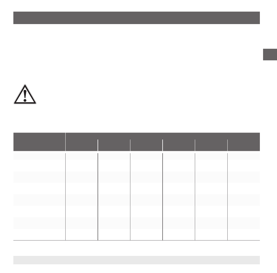
2.4 Output signal/current parameters
Parameter
Output signal
4 ... 20 mA
(2-wire)
20 … 4 mA
(2-wire)
DC 1 … 5 V
DC 1 … 6 V
DC 0.5 … 4.5 V DC 0.5 … 4.5 V
ratiometric
Span range
16 mA
16 mA
4 V
5 V
4 V
4 V * U
B
/ 5 V
Control range lower limit
value
3.6 mA
23 mA
-0.4 V
-0.4 V
-0.4 V
0.1 * U
B
/ 5 V
Span
Initial limit value
3.8 mA
20.5 mA
0.9 V
0.9 V
0.4 V
0.4 V * U
B
/ 5 V
Span
Initial nominal value
4 mA
20 mA
1 V
1 V
0.5 V
0.5 * U
B
/ 5 V
Span
Final nominal value
20 mA
4 mA
5 V
6V
4.5 V
4.5 * U
B
/ 5 V
Span
Final limit value
20.5 mA
3.8 mA
5.5 V
6.5 V
4.7 V
4.7 V * U
B
/ 5 V
Control range upper limit
value
23 mA
3.6 mA
11.5 V
11.5 V
11.5 V
4.9 * U
B
/ 5 V
Nominal operating voltage
U
B
[V DC]
24
24
24
24
24
5
2. Safety