4 mounting, 1 mounting steps, 4mounting – WIKA IPT-11 User Manual
Page 9
4
Mounting
4
.1 Mounting steps
The indicating and adjustment module can be inserted or removed at
any time. It is not necessary to interrupt the voltage supply.
For mounting, proceed as follows:
1
Unscrew the housing cover
2
Place the indicating/adjustment module in the requested position
on the electronics
Information:
Four different positions are possible, each displaced by 90°.
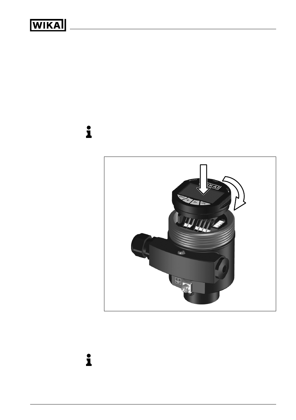
Fig. 3: Mounting the indicating and adjustment module
3
Press the indicating/adjustment module lightly onto the electronics
and turn it to the right until it snaps in
4
Screw housing cover with inspection window tightly back on
Note:
If you intend to retrofit the instrument with an indicating and adjustment
module for continuous measured value indication, a higher cover with
an inspection glass is required.
Mount/Dismount indicat-
ing and adjustment
module
Indicating and adjustment module for IPT-1* sensors
9
4 Mounting
31549
-
EN
-081211