Figure 6 – DuraVent Combustion Air Systems for PelletVent Pro User Manual
Page 8
8
finally, install the lower front
portion over the lower Back and Upper front
portions (Fig 7). the notched end of the lower
front portion must face downward, and the
holes on the sides of the lower front portion
will be at the top. Secure the lower front
portion with (2) 3/8” black screws in the two
side holes. Pre-drill the holes in the other
portions, where needed.
If a Channel shorter than 36” is
required for your installation, the Adjustable
Wall Channel install can be cut using tin snips.
Use only the lower Back and lower front
portions, and trim the upper ends only for both
portions (Fig 8). Cutting the other ends will
prevent the Channel tee from fitting properly.
for this installation, the lower Back and lower
front portions will fit on the outside (not within)
of the opening in the Wall thimble. the holes
on the sides of the Wall Channel will need to
Figure 7
Figure 7
INTERIOR
LOWER FRONT
PORTION COVERS
OVER UPPER
PORTION. ALIGN
WITH LOWER
BACK PORTION
AND SECURE WITH
(2) 3/8" SCREWS
THROUGH SIDE
HOLES.
SLIDE LOWER
BACK PORTION
BEHIND UPPER
PORTION AND
ADJUST TO
HEIGHT NEEDED.
SECURE TO WALL
USING (2) 1-1/2"
SCREWS THROUGH
BOTTOM DIMPLES.
EXTENDED EDGE
AT BOTTOM
SlIDe lOWer BACK
POrtIOn BeHInD
UPPer POrtIOn AnD
ADJUSt tO HeIGHt
neeDeD. SeCUre tO
WAll USInG (2) 1-1/2"
SCreWS tHrOUGH
BOttOm DImPleS.
lOWer frOnt
POrtIOn COVerS
OVer UPPer POrtIOn.
AlIGn WItH lOWer
BACK POrtIOn AnD
SeCUre WItH (2) 3/8"
SCreWS tHrOUGH
SIDe HOleS.
eXtenDeD eDGe
At BOttOm
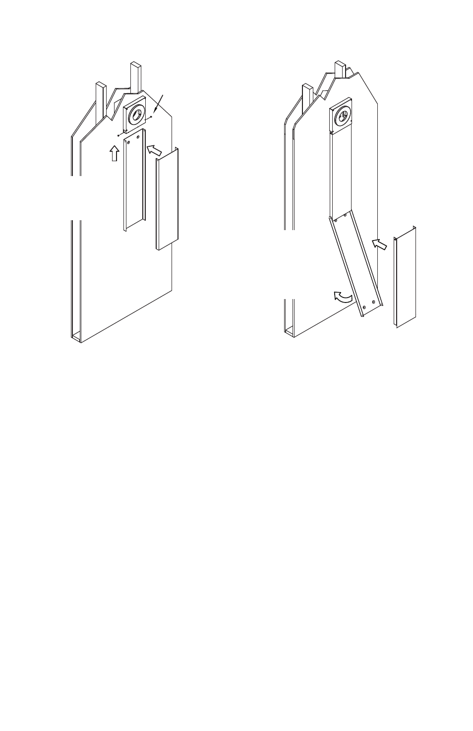
Figure 6
Figure 6
ALIGN HOLES IN
UPPER BACK
PORTION WITH
HOLES IN WALL
THIMBLE.
ALIGN HOLES IN
UPPER FRONT
PORTION WITH
HOLES IN UPPER
BACK PORTION
AND WALL
THIMBLE
SECURE CHANNEL
TEE TO WALL
THIMBLE WITH (2)
3/8" SCREWS
INTERIOR
SECURE UPPER
BACK PORTION
OF WALL
CHANNEL TO
WALL WITH (2)
1-1/2" WOOD
SCREWS THROUGH
DIMPLES
SeCUre CHAnnel
tee tO WAll WItH
(2) 3/8" SCreWS
AlIGn HOleS In
UPPer frOnt
POrtIOn WItH
HOleS In UPPer
BACK POrtIOn
AnD WAll tHImBle
SeCUre UPPer
BACK POrtIOn
Of WAll
CHAnnel tO
WAll WItH (2)
1-1/2" WOOD
SCreWS
tHrOUGH
DImPleS
AlIGn HOleS
In UPPer BACK
POrtIOn WItH
HOleS In WAll
tHImBle
Second, install the Upper front
portion by sliding the top end into the Wall
thimble. the Upper front portion will install
over the Upper Back portion, but inside the
Wall thimble. Align the holes on the sides with
the holes in the Wall thimble and secure in
place with (2) 3/8” black screws provided (Fig
6).
next, install the lower Back portion
by sliding it behind the Upper Back portion
(Fig 7). the bottom wall portion will fit on the
outside of the Upper front portion. Adjust
its position to the desired length of your
installation. remember to account for the
height of the Channel tee (installed in Step 5)
when determining the correct length for your
installation. Secure the bottom wall portion
against the wall with (2) 1-1/2” wood screws
through the bottom two dimples.