DuraVent Combustion Air Systems for PelletVent Pro User Manual
Page 6
6
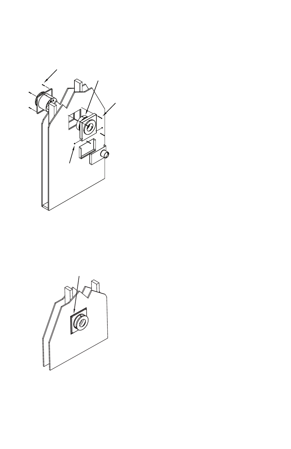
Step 3. Install the CAS Wall thimble. Cut
and frame a 7-1/2” x 7-1/2” opening in the
wall at the location determined for the CAS
Wall thimble. Inside the home, install the
black-painted interior portion of the CAS Wall
thimble into the opening, centered within the
framing. make sure the air-inlet channel faces
downwards. Secure the interior portion of the
CAS Wall thimble with (4) 2-1/2” long wood
screws. On the exterior of the home, install
the non-painted exterior portion of the CAS
Wall thimble. the tubular radiation shield of
the exterior portion slides into the radiation
shield of the interior portion within the framed
opening. Important: Be sure the air-inlet
openings of the outer half of the wall thimble
face downwards to prevent rain and snow
infiltration (Fig 2). Secure the exterior portion
of the CAS Wall thimble to the wall with (4)
1-1/2” wood screws. Seal the perimeter edge
of the Wall thimble where it meets the wall
with a waterproof sealant (Fig 3). Important:
Do not place anything inside the Wall thimble
other than PelletVent pipe. the space around
the vent pipe inside the thimble must remain
empty to prevent overheating the Wall thimble
and to enable proper air flow to the appliance.
the CAS Wall thimble can
accommodate up to 6-1/2” thick walls. If
installed in a thicker wall, a field-fabricated
extension tube for the radiation shield must be
installed. the extension tube can be made out
of minimum of 26 gauge galvanized steel. the
CAS Wall thimble must have a continuous
connection between the interior and exterior
portions of the CAS Wall thimble (Fig 4).
Step 4. Install the CAS Adjustable Wall
Channel, if needed. If the Adjustable Wall
Channel is not needed for the installation, skip
this step and continue with Step 5. If the Wall
thimble is installed above the appliance, the
Figure 2
Figure 3
SeAl ArOUnD eDGe Of
eXterIOr WAll tHImBle
WItH nOn-HArDenInG
WAterPrOOf SeAlAnt
Figure 2
SECURE WITH (4)
1-1/2" SCREWS
TUBULAR RADIATION SHIELD
EXTENDS INSIDE FRAMED
OPENING. DO NOT PLACE
ANYTHING INSIDE RADIATION
SHIELD OTHER THAN THE
VENT PIPE.
SECURE WITH (4)
2-1/2" SCREWS
SECURE CHANNEL
TEE TO WALL
THIMBLE WITH (2)
3/8" SCREWS
INTERIOR
EXTERIOR
Figure 3
EXTERIOR
SEAL AROUND EDGE OF
EXTERIOR WALL THIMBLE
WITH NON-HARDENING
WATERPROOF SEALANT
SeCUre
WItH (4) 1-1/2"
SCreWS
tUBUlAr rADIAtIOn
SHIelD eXtenDS InSIDe
frAmeD OPenInG. DO
nOt PlACe AnytHInG
InSIDe rADIAtIOn
SHIelD OtHer tHAn tHe
Vent PIPe.
SeCUre CHAnnel
tee tO WAll
tHImBle WItH (2)
3/8" SCreWS
SeCUre
WItH (4) 2-1/2"
SCreWS