Figure 4 – DuraVent Combustion Air Systems for PelletVent Pro User Manual
Page 7
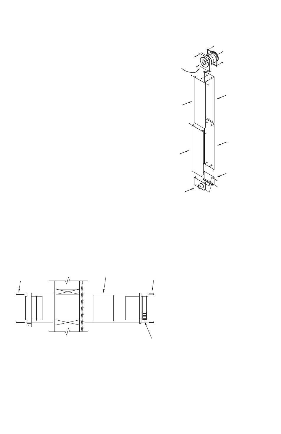
Figure 4
EXTERIOR
INTERIOR
FOR WALLS THICKER THAN
6-1/2", FIELD FABRICATE
RADIATION TUBE
EXTENSION OF MINIMUM
26-GA GALVANIZED STEEL
ENSURE AIR INLET OPENINGS
ARE FACING DOWN ON WALL
THIMBLE
SECURE WITH (4)
1-1/2" SCREWS
SECURE WITH (4)
2-1/2" SCREWS
7
Adjustable Wall Channel is needed to extend
from the Wall thimble down to the appliance.
Determine the distance from the
Wall thimble to the appliance. the Adjustable
Wall Channel can only be installed in a vertical
direction and can adjust from 36” to 70”.
the Adjustable Wall Channel is
composed of 4 parts: Upper Back portion,
Upper front portion, lower Back portion,
and lower front portion (Fig 5). It is highly
recommended that you use waterproof sealant
inside the Wall thimble’s air inlet channel to
prevent possible condensate leakage. first,
place the Upper Back portion inside the
opening of the Wall thimble. Align the Upper
Back piece so the dimples are at the top and
the holes on the sides match up with the holes
on the sides of the Wall thimble. Be sure to
allow a small gap on both sides as the Upper
front portion fits inside the Wall thimble,
installed next. Secure the Upper Back piece to
the wall using (2) 1-1/2” wood screws through
the dimple standoffs against the wall (Fig 6).
Figure 5
Figure 5
WALL THIMBLE,
INTERIOR PORTION
WALL CHANNEL,
UPPER BACK
PORTION. NOTE
DIMPLES ARE AT
TOP.
WALL CHANNEL,
UPPER FRONT
PORTION. NOTE
SIDE HOLES ARE
AT TOP.
WALL CHANNEL,
LOWER FRONT
PORTION. NOTE
EXTENDED EDGE
FACES DOWN AND
SIDE HOLES ARE
AT TOP.
WALL CHANNEL,
LOWER BACK
PORTION
CHANNEL TEE
BACK PORTION
CHANNEL TEE
FRONT FACEPLATE
WALL THIMBLE,
EXTERIOR PORTION
USE WATERPROOF
SEALANT INSIDE WALL
THIMBLE AIR CHANNEL
OPENING TO PREVENT
POSSIBLE CONDENSATE
LEAKAGE
SeCUre
WItH (4)
1-1/2"
SCreWS
WAll tHImBle
eXterIOr POrtIOn
WAll CHAnnel,
UPPer BACK POrtIOn.
nOte: DImPleS Are
At tOP.
WAll CHAnnel,
lOWer BACK POrtIOn
CHAnnel tee,
BACK POrtIOn
CHAnnel tee,
frOnt fACePlAte
WAll CHAnnel,
UPPer frOnt
POrtIOn. nOte: SIDe
HOleS Are At tOP.
USe WAterPrOOf
SeAlAnt InSIDe
WAll tHImBle AIr
CHAnnel OPenInG tO
PreVent POSSIBle
COnDenSAte
leAKAGe
WAll CHAnnel,
lOWer frOnt
POrtIOn. nOte:
eXtenDeD eDGe
fACeS DOWn AnD
SIDe HOleS Are
At tOP.
WAll tHImBle
InterIOr POrtIOn
SeCUre
WItH (4) 2-1/2"
SCreWS
Figure 4
fOr WAll tHICKer tHAn 6-1/2",
fIelD fABrICAte rADIAtIOn
tUBe eXtenSIOn Of mInImUm
26-GA GAlVAnIzeD Steel
enSUre AIr Inlet
OPenInGS Are fACInG
DOWn On WAll tHImBle