American Standard 7271.521 User Manual
Page 3
M 9 6 8 4 8 4
1
2
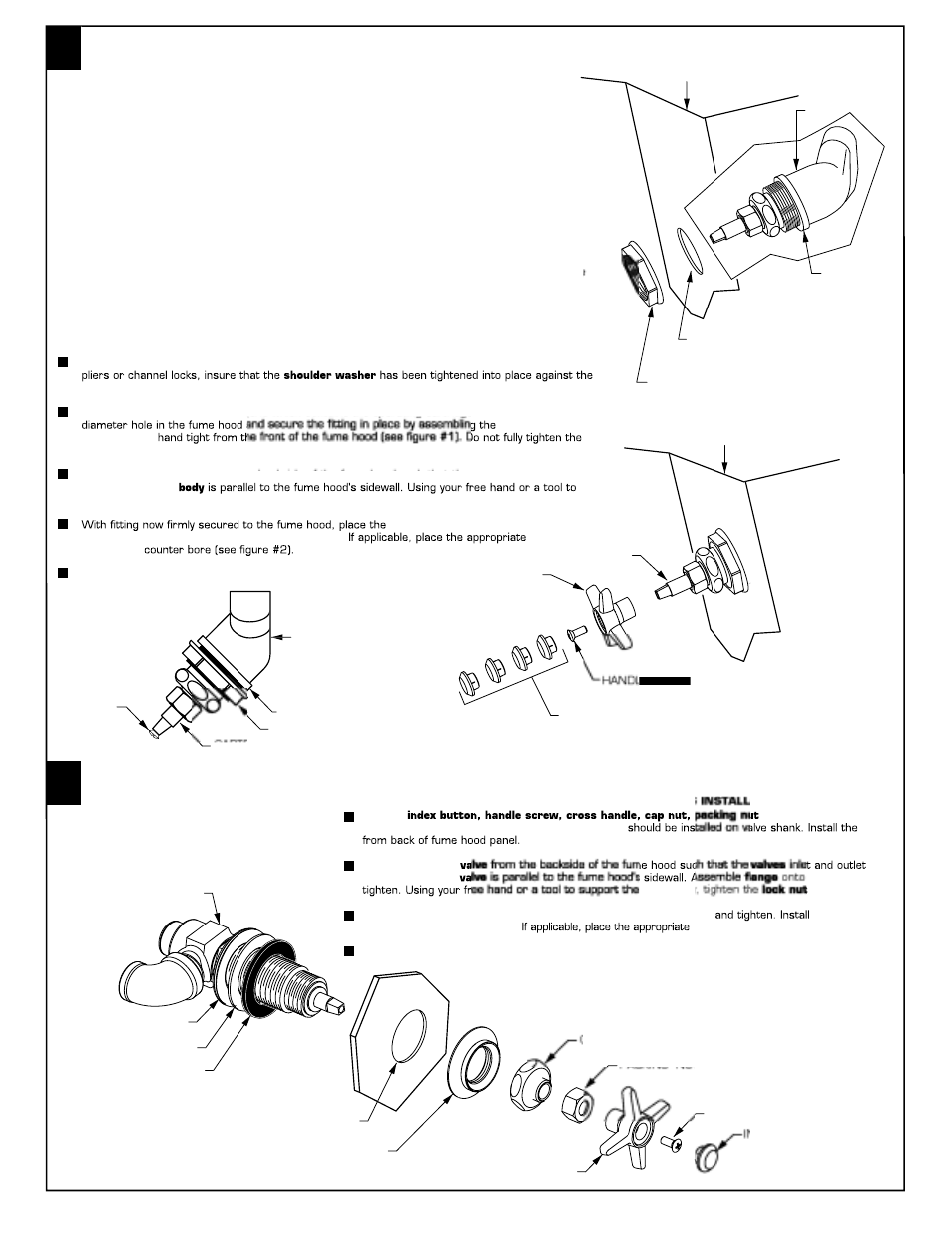
BODY
SHOULDER WASHER
HOLD DOWN NUT
CARTRIDGE STEM
HANDLE
SCREW
Important service note:
The Faucet Panel mounted fume hood fitting has been designed such that future servicing of the
fitting's cartridge can be done from the (user's) side of the fume hood. To do this, insure that the
main supply valve to the fitting has been completely turned off and then purged by completely
opening the fitting and releasing trapped material into the fume hood atmosphere. Then, support
the entire fitting by holding the hold-down nut in place with a wrench, before loosening the
cartridge's cap nut.
This Panel mounted fume hood valve has been shipped as shown below to ease installation. It is
designed to be installed in a 45
˚
angled fume hood equipped with 1-1/2" (38.1mm) diameter
˚
mounting holes. Before proceeding with the installation, identify and familiarize yourself with all
of the components.
Important Note: The front load fume hood fittings described in these installation instructions
are available in both right hand and left hand models. Right hand models are marked on both
sides of the body with an "R" and left hand models are similar marked with an "L". Due to the
use of these fittings in both right and left hand fume hoods, the bodies are marked on both
sides with directional flow arrows. Regardless of the model used, the fittings are designed to
be installed such that the inlet is on the bottom.
45
˚
ANGLED
FUME HOOD
LOCK NUT
FLANGE
VALVE
HOOD MOUNTING HOLE
CROSS HANDLE
CAP NUT
PACKING NUT (7271.571 and 7271.521 ONLY)
INSTALL FRONT-LOADED ANGLE CONTROL VALVE, 7271.021/521
(AIR, GAS, VACUUM, WATER)
INSTALL FRONT-LOADED VALVE FOR STRAIGHT PANELS, 7271.071/571
(AIR, GAS, VACUUM, WATER)
HANDLE SCREW
NDEX BUTTON
STEEL WASHER
RUBBER WASHER
BODY
FIGURE 1
SHOULDER
WASHER
1-1/2" (38.1mm)
MOUNTING HOLE
HOLD DOWN NUT
Remove
and flange from valve.
Rubber seal washer, steel washer and lock nut
valve
Align the mounted
are in line and the
valve and
valve body
securely.
With valve now firmly secured to the fume hood install the cap nut
cross handle
and secure with handle screw.
index button into handle counter bore.
Complete the inlet and outlet piping to the valve and check for leaks.
INDEX BUTTONS
(AIR, GAS, VACUUM, WATER)
HANDLE
STEM
FIGURE 2
45
˚
ANGLED
FUME HOOD
IMPORTANT: FLUSH ALL SUPPLY LINES PRIOR TO FITTING INSTALLATION.
IMPORTANT: FLUSH ALL SUPPLY LINES PRIOR TO FITTING INSTALLATION.
Remove the hold-down nut from the body and the
y
handle screw from the stem. With a pair of
body such that the threads on the two components lock together.
y
Place the front end of the body (end which contains the operating cartridge) through the 1-1/2"
y
hold-down nut
onto the body
hold-down nut at this time.
Align the mounted fitting from the backside of the fume hood such that the body's inlet and outlet
are in line and the
support the valve body from the backside, tighten the
y
hold-down nut securely.
handle onto the stem and tighten it
into place with the screw removed from the stem.
index button
into handle
Complete the inlet and outlet piping to the fitting and check for leaks.