Section – Kramer Electronics TP-126xl User Manual
Page 9
6
TP-125xl/TP-126xl - Defining the TP-125xl/TP-126xl Line Transmitter and Receiver
4.1
Defining the TP-125xl UXGA/Audio/Data Line
Transmitter
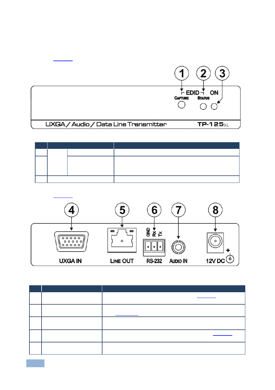
defines the front panel of the TP-125xl.
Figure 1: TP-125xl UXGA/Audio/Data Line Transmitter Front Panel
#
Feature
Function
1
EDID
CAPTURE Button
Press to capture the EDID from the video display
2
STATUS LED
Indicates the following EDID status:
Flashes slowly then lights solid
—new EDID stored
Flashes quickly then lights solid
—default EDID stored
3
ON LED
Lights green when the device is powered on
defines the rear panel of the TP-125xl.
Figure 2: TP-125xl UXGA/Audio/Data Line Transmitter Rear Panel
#
Feature
Function
4
UXGA IN 15-pin HD
Connector (F)
Connect to a computer graphics source (see
5
LINE OUT RJ-45
Connector
Connect to the Line In RJ-45 connector on the TP-126xl
(see
6
RS-232 Serial Port 3-pin
Terminal Block
Connect to an RS-232 device (PC or controller).
Note: The RS-232 link is bidirectional
7
AUDIO IN 3.5mm Mini
Jack
Connect to an unbalanced, stereo audio source (see
8
12V DC Power Connector
Connect to one of the supplied +12V DC power adapters. Center
pin positive