Wiring the cat 5 line in/line out rj-45 connectors, Figure 4: connecting multiple devices, Figure 5: cat 5 pinout – Kramer Electronics TP-200AXR User Manual
Page 13: Table 3: cat 5 pinout, Nout is defined in, Table 3, Figure 5, Figure 4, Could be powered by two p, Connecting the pc/audio line transmitter/receiver
Connecting the PC/Audio Line Transmitter/Receiver
11
11
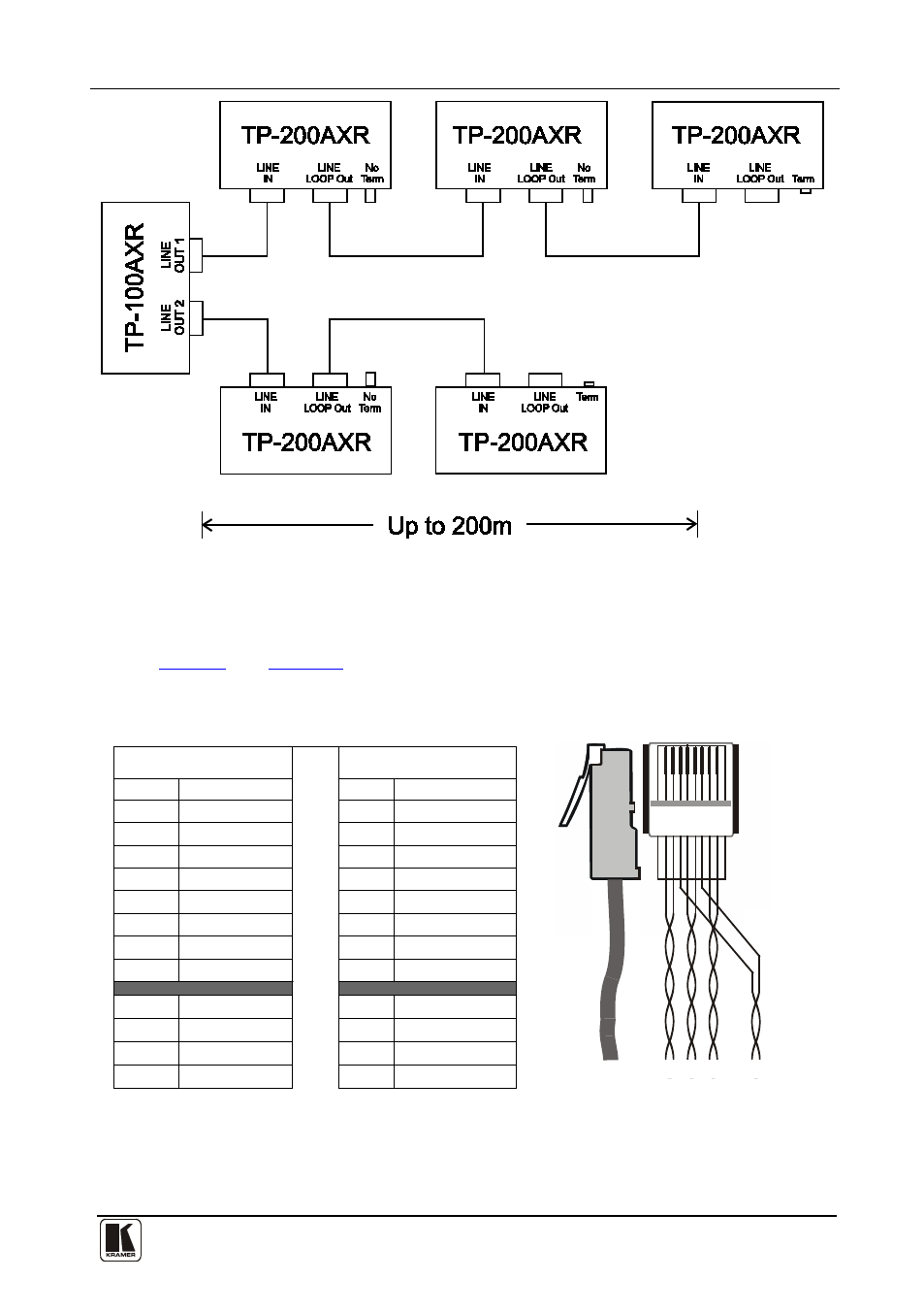
Figure 4: Connecting Multiple Devices
5.3 Wiring the CAT 5 LINE IN/LINE OUT RJ-45 Connectors
define the UTP CAT 5 PINOUT, using a straight pin
to pin cable with RJ-45 connectors:
Table 3: CAT 5 PINOUT
Figure 5: CAT 5 PINOUT
36
78
12
5
4
1
45 78
6
3
2
EIA /TIA 568A
EIA /TIA 568B
PIN
Wire Color
PIN
Wire Color
1
Green/White
1
Orange/White
2
Green
2
Orange
3
Orange/White
3
Green/White
4
Blue
4
Blue
5
Blue/White
5
Blue/White
6
Orange
6
Green
7
Brown/White
7
Brown/White
8
Brown
8
Brown
Pair 1
4 and 5
Pair 1 4 and 5
Pair 2 3 and 6
Pair 2 1 and 2
Pair 3
1 and 2
Pair 3 3 and 6
Pair 4
7 and 8
Pair 4 7 and 8
This manual is related to the following products: