1 wiring the tp line in/line out rj-45 connectors, Wiring the tp line in/line out rj-45 connectors, Figure 4: tp pinout wiring – Kramer Electronics PT-572+ User Manual
Page 12
PT-571/PT-572+ - Connecting the PT-571 and PT-572+ Transmitter Receiver Pair
9
9
4. Connect the 12V DC power adapter to the power socket on the PT-571
and/or the PT-572+ and connect the adapter to the mains electricity (not
shown in
).
Note: When connecting the PT-572+ to the VP-81SID do not connect the
12V power supply to the PT-572+.
6.1
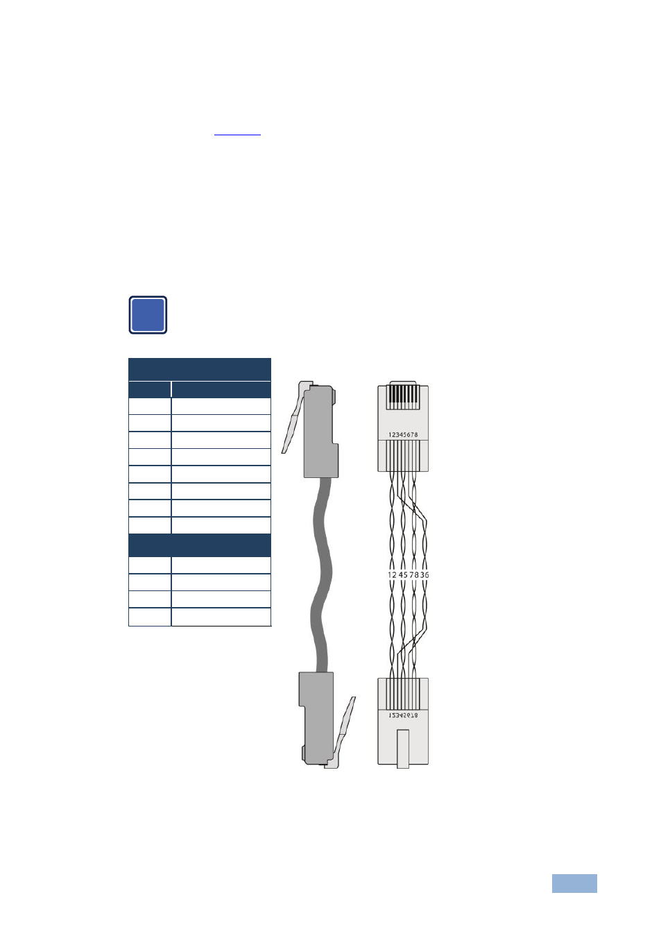
Wiring the TP Line In/Line Out RJ-45 Connectors
This section defines the TP pinout, using a straight pin-to-pin cable with RJ-45
connectors.
Note, that the cable Ground shielding must be connected / soldered to
the connector shield.
EIA /TIA 568B
Figure 4: TP Pinout Wiring
PIN
Wire Color
1
Orange / White
2
Orange
3
Green / White
4
Blue
5
Blue / White
6
Green
7
Brown / White
8
Brown
Pair 1
4 and 5
Pair 2
1 and 2
Pair 3
3 and 6
Pair 4
7 and 8
i