9 communication protocol, Communication protocol, Table 5: structure of the protocol – Kramer Electronics SP-12HD User Manual
Page 18: 9communication protocol
KRAMER: SIMPLE CREATIVE TECHNOLOGY
Communication Protocol
16
9
Communication Protocol
RS-232 communication between the SP-12HD and the PC is performed
using this protocol (VER 0.1). The protocol
The controller and the machine should be connected via a null-modem
connection, that is, if using a 9-pin D-sub port, connect pin 5 of the PC to
pin 5 of the machine, cross pins 2 and 3, that is, connect pin 2 of the PC to
pin 3 of the machine, and connect pin 3 of the PC to pin 2 of the machine.
On the PC side, short pins 4 and 6, and short pins 1, 7 and 8.
uses four bytes of information,
and transmission settings are 9600 baud, no parity, 8 data bits and 1 stop bit.
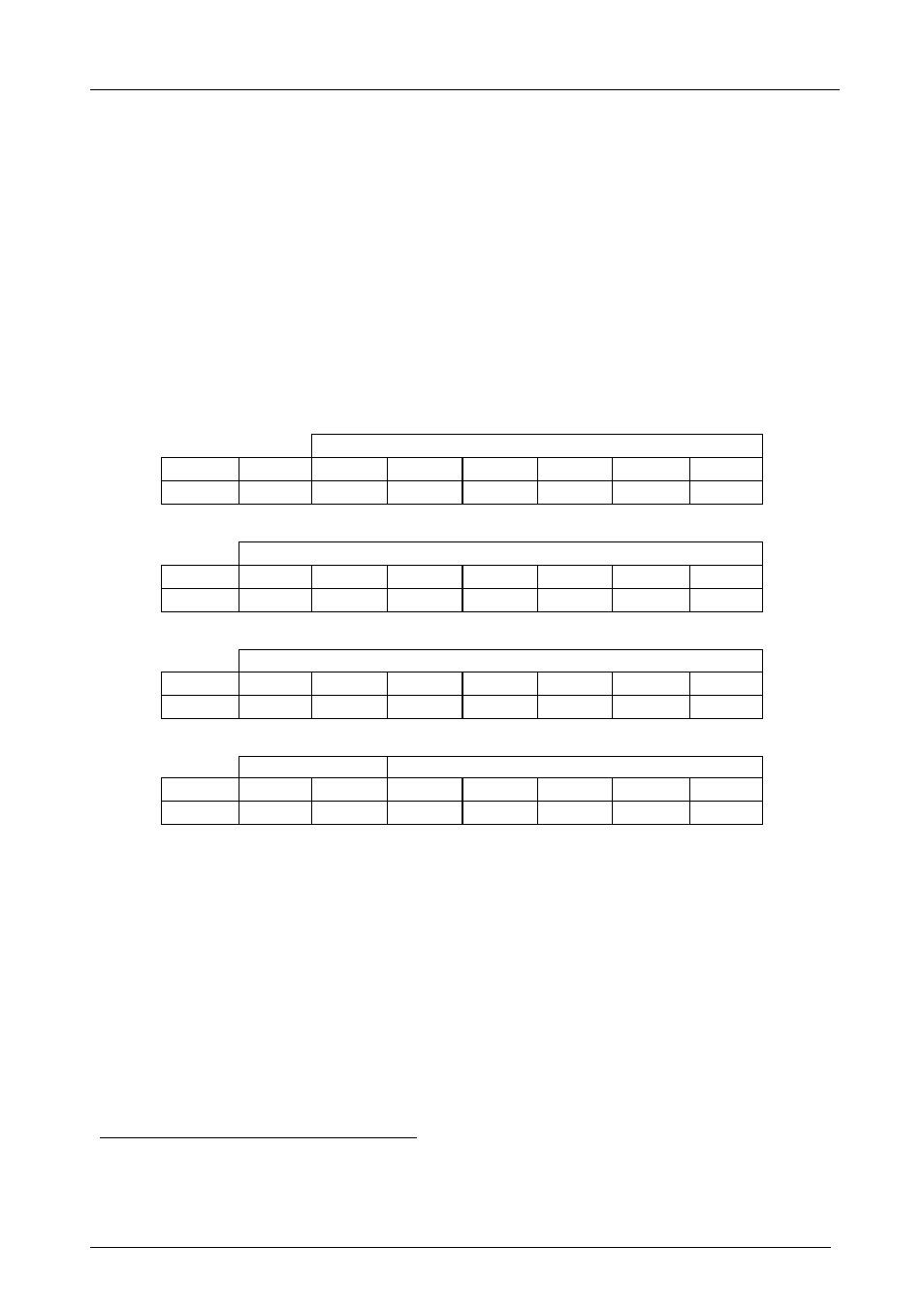
Table 5: Structure of the Protocol
MSB
LSB
INSTRUCTION
0
TO PC
I5
I4
I3
I2
I1
I0
7
6
5
4
3
2
1
0
Byte 1
DATA
1
D6
D5
D4
D3
D2
D1
D0
7
6
5
4
3
2
1
0
Byte 2
EXTENDED DATA
1
E6
E5
E4
E3
E2
E1
E0
7
6
5
4
3
2
1
0
Byte 3
MSBs
ADDR
1
E7
D7
1
1
0
0
0
7
6
5
4
3
2
1
0
Byte 4
Note that the MSBs of the DATA (D7) and the EXTENDED DATA (E7) are in the fourth byte.
Terminology:
TO PC is the “DESTINATION BIT”
I4..I0 is the “INSTRUCTION”
D7..D0 is the “DATA”
E7..E0 is the “EXTENDED DATA”
The destination bit, TO PC, is 0 when sending from the PC to the machine, or 1 when sending from the machine
to the PC.
1 This protocol complements Kramer’s “Protocol 2000” (Kramer’s switcher protocol), that is, the two protocols can co-exist
without disturbing one another (according to Protocol 2000’s definitions, the SP-12HD would be machine number 24).