Your rc-7rl / rc-7rle – Kramer Electronics RC-7RL User Manual
Page 7
Your RC-7RL / RC-7RLE
5
4.2 Defining the RC-7RLE Front Panel
Figure 2 and Table 2 define the
RC-7RLE front panel:
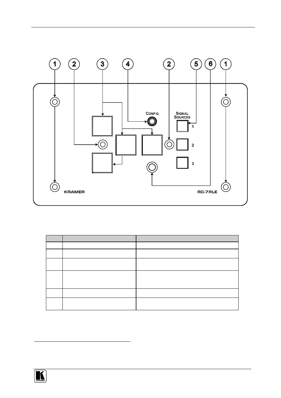
Figure 2: RC-7RLE Front Panel
Table 2: RC-7RLE Front Panel
#
Feature
Function
1
Mounting holes (4)
For fastening the controller in place
2
Faceplate Attachment Holes (2)
For attaching the faceplate to the controller
1
3
Configurable Control Buttons (4) Macro Buttons for controlling the room and the
A/V equipment
4
CONFIG
Port
2
on 3.5mm jack
connector
Used for Windows®-based configuration
software (driver downloads, firmware updates
and so on)
5
SIGNAL SOURCES
Buttons
Select the input source (from 1 to 3)
6
IR IN
Receiver
Accepts IR remote commands (for the IR-
learner feature)
3
1 These screws should not be removed during or after mounting
2 Via the front panel, without having to remove the RC-7RLE from its mounting
3 Letting you configure the RC-7RLE directly from the remote transmitter without the need for software
- VM-114H (22 pages)
- VM-114H2C (25 pages)
- VM-114H4C (23 pages)
- VS-81ETH (27 pages)
- VS-81ETH (41 pages)
- VM-9T (13 pages)
- VP-12NHD (15 pages)
- VP-5R (20 pages)
- VP-6A (15 pages)
- PT-5R/T (13 pages)
- TP-102HD (13 pages)
- TP-104HD (33 pages)
- TP-112HD (13 pages)
- TP-114 (13 pages)
- TP-202 (15 pages)
- TP-205A (15 pages)
- TP-210 (14 pages)
- TP-210A (15 pages)
- tp-219hd (16 pages)
- TP-305A (15 pages)
- TP-310A (18 pages)
- TP-410 (34 pages)
- VM-1H4C (17 pages)
- VP-200xlT (31 pages)
- VP-300THD (12 pages)
- VPM-2 (42 pages)
- SI-1VGA (2 pages)
- SID-DP (2 pages)
- SID-DVI (2 pages)
- SID-H (2 pages)
- SID-VGA (2 pages)
- SID-X1 (2 pages)
- SID-X1 (23 pages)
- SID-X1N (23 pages)
- SID-X2N (31 pages)
- SID-X3N (22 pages)
- 622R (17 pages)
- VS-169TP (7 pages)
- VS-169TP (45 pages)
- WSI-1VGA (2 pages)
- TP-107AV (32 pages)
- WP-500 (2 pages)
- SV-552 (22 pages)
- WP-501 (16 pages)
- RC-62 (94 pages)