Kramer Electronics RC-13TC User Manual
Page 7
RC-13TC - Defining the RC-13TC Video Transport Controller
5
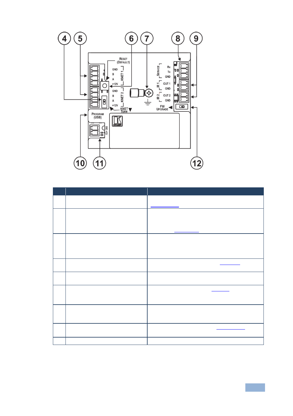
Figure 2: RC-13TC Video Transport Controller Rear Panel
#
Feature
Function
4
KNET TERM Termination Switch
Use to set the K-NET bus termination (see
Section 5.2.2
5
KNET 4-pin Removable Terminal
Blocks (1 and 2)
Connect to a master room controller or to another
auxiliary device.
Connect GND to GND, B to B, A to A, +12V to
+12V (see
Section 5.2
6
RESET (DEFAULT) Factory
Default Reset Button
Press and hold during power-up to erase all
custom programming.
Note: The current LCD text and all button actions
are erased
7
Ring Tongue Terminal Grounding
Screw
Connect to grounding wire (see
Section 6
8
RS-232 3-pin Removable
Terminal Block
For controlling a display, switcher, AV source or
other AV equipment
9
IR Infrared 2-pin Removable
Terminal Blocks (1 and 2)
Connect to IR emitters (see
Connect OUT 1 or OUT 2 to IR+ (anode), GND to
GND (cathode)
10 PROGRAM (USB) Connector
Connect to a computer to program the unit ID,
LCD text and button actions using K-Config
Configuration software
11 Power Supply 2-pin Removable
Terminal Block
Connect to power supply (see
Section 5.1.2
Connect GND to GND, +12V to +12V
12 FW UPGRADE Switch
For the use of Kramer service personnel only