On 5.1.2 – Kramer Electronics RC-13TC User Manual
Page 9
RC-13TC - Using Your Video Transport Controller
7
When the
RC-13TC functions as a standalone, wall mounted video transport
controller, as illustrated in
•
The
RC-13TC is connected directly to the controlled devices (see
Section 5.1.1
•
A +12V DC power supply to the unit is required (see
Section 5.1.2
•
The
RC-13TC requires programming
5.1.1
Connecting the RC-13TC as a Standalone Video Transport
Controller
The
RC-13TC can be connected as a standalone video transport controller as
illustrated in the example in
with connections as described in the following
table:
Your system integrator configures and installs your room controller to suit your requirements.
This example describes only one possible configuration.
Connector
Connect to:
GND/+12V
Power adapter
IR 1
Blu-ray DVD player 1
IR 2
Blu-ray DVD player 2
PROGRAM (USB)
PC—required only for configuring the
RC-13TC
RS-232
Display or switcher
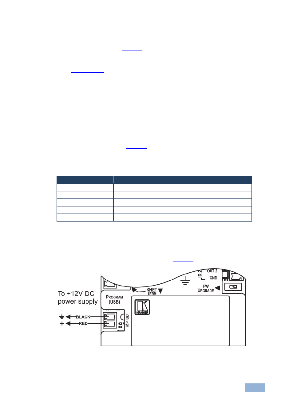
5.1.2
Connecting a Standalone RC-13TC to a Power Supply
When the
RC-13TC is employed as a standalone room controller it should be
connected to the power supply as illustrated in
Figure 4: RC-13TC Standalone Power Supply Connection