9 communication protocol, Communication protocol, Table 6: protocol definitions – Kramer Electronics VS-626 User Manual
Page 23
Communication Protocol
KRAMER: SIMPLE CREATIVE TECHNOLOGY
20
9 Communication Protocol
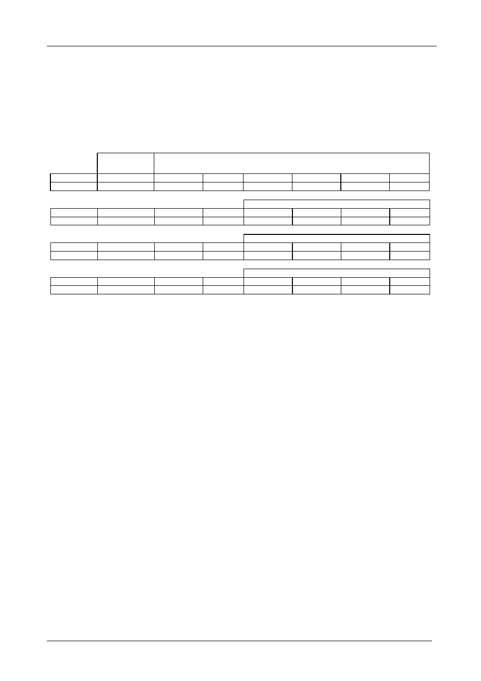
Communication with the Matrix Switchers described in this manual uses four
bytes of information as defined in Table 6 Data is transferred at 9600 baud
with no parity, 8 data bits and 1 stop bit.
Table 6: Protocol Definitions
MSB
LSB
DESTINATIO
N
INSTRUCTION
0
D
N5
N4
N3
N2
N1
N0
7
6
5
4
3
2
1
0
1st byte
INPUT
1
0
0
0
I3
7
6
5
4
3
2nd byte
OUTPUT
1
0
0
0
O3
7
6
5
4
3
3rd byte
MACHINE NUMBER
1
0
0
0
0
M2
M1
7
6
5
4
3
2
1
4th byte
1st BYTE:
Bit 7 – Defined as 0.
D – “DESTINATION”
This bit is always "low", when sending from the PC to the Matrix Switchers, and "high" for information
sent to the PC.
N5…N0 – “ INSTRUCTION”.
The function that is to be performed by the Matrix Switcher(s) is defined by the INSTRUCTION 6 bits. Similarly, if a function is
performed via the machine’s keyboard, then these bits are set with the INSTRUCTION NO., which was performed. The instruction
codes are defined according to the table below (INSTRUCTION NO. is the value to be set for N5…N0).
2nd BYTE: Bit 7 – Defined as 1.
Bits 4 – 6 - Defined as 0.
I3… I0 – “ INPUT”.
When switching via RS-232 for RS- 485 (for instruction codes 1 and 2), these bits set the input that is to be switched. Similarly, if
switching is done via the machine’s front panel, then these bits are set with the INPUT NUMBER which was switched. For disconnect,
set as 0. For other operations, these bits are defined according to the table.
3rd BYTE: Bit 7 – Defined as 1.
Bits 4 – 6 Defined as 0.
O3…O0 – “OUTPUT”.
When switching via RS-232 or RS-485 (for instruction codes 1 and 2), the output to switch is set by these bits. Similarly, if switching is
done via the machine’s front panel, then these bits are set with the OUTPUT NUMBER which was switched. For other operations, these
bits are defined according to the table.
4th BYTE: Bit 7 – Defined as 1.
Bits 3 – 6 Defined as 0.
M2… M0 – “Machine Number”.
Machine Number = (DIP – Switch Code) + 1.