Vs-201yc communication protocol – Kramer Electronics VS-201YC User Manual
Page 17
VS-201YC Communication Protocol
15
When switching (ie. instruction codes 1 and 2), the OUTPUT (7 bits) is set as the output number which is to be switched.
Similarly, if switching is done via the machine’s front-panel, then these bits are set with the OUTPUT NUMBER which was
switched. For other operations, these bits are defined according to the table.
4
th
BYTE: Bit 7 – Defined as 1.
Bit 5 – Don’t care.
OVR – Machine number override.
M4…M0 – MACHINE NUMBER.
Used to address machines in a system via their machine numbers. When several machines are controlled from a single serial
port, they are usually configured together with each machine having an individual machine number. If the OVR bit is set, then
all machine numbers will accept (implement) the command, and the addressed machine will reply.
For a single machine controlled via the serial port, always set M4…M0 = 1, and make sure that the machine itself is
configured as MACHINE NUMBER = 1.
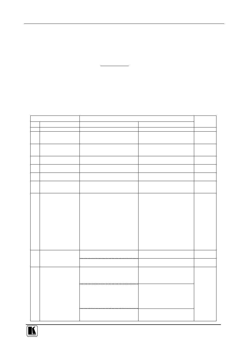
Table 6: Instruction Codes for Protocol 2000
Note: All values in the table are decimal, unless otherwise stated.
INSTRUCTION
DEFINITION FOR SPECIFIC INSTRUCTION
#
DESCRIPTION
INPUT
OUTPUT
NOTE
0 RESET VIDEO
0
0
1
1 SWITCH VIDEO
Set equal to video input which is to
be switched
(0 = disconnect)
Set equal to video output which is
to be switched
(0 = to all the outputs)
2, 15
2 SWITCH AUDIO
Set equal to audio input which is to
be switched
(0 = disconnect)
Set equal to audio output which
is to be switched
(0 = to all the outputs)
2
3 STORE VIDEO
STATUS
Set as SETUP #
0 - to store
1 - to delete
2, 3, 15
4 RECALL VIDEO
STATUS
Set as SETUP #
0
2, 3, 15
5 REQUEST STATUS
OF A VIDEO OUTPUT
Set as SETUP #
Equal to output number whose
status is reqd
4, 3
6 REQUEST STATUS
OF AN AUDIO
OUTPUT
Set as SETUP #
Equal to output number whose
status is reqd
4, 3
7 VIS SOURCE
Set as input # when
OUTPUT byte = 6;
OR
set as output # when
OUTPUT byte = 7;
OR
set as blank period
(in steps of 25ms) when
OUTPUT byte = 32;
OR
set = 0. *****
0 - No VIS (immediate)
1 - Input # 1
2 - External digital sync
3 - External analog sync
4 - Dynamic sync
5 - Inter-machine sync
6 - Input # (INPUT byte)
7 - Output #(INPUT byte)
8 - User-defined sync
32 - RGBHV seamless switching
64 - Set for delayed switch
65 - Execute delayed switch
66 - Cancel delayed switch
setting
2, 5, 17, 18
BREAKAWAY
SETTING
0
0 - audio-follow-video
1 - audio breakaway
2
8
1
0 - FOLLOW mode
1 - Normal mode
15
VIDEO / AUDIO TYPE
SETTING
0 - for video
0 - CV
1 - YC
2 - YUV
3 - RGBS
4 - SDI
5 - CV+YC
6 - VGA scaler
7 - DVI
1 - for audio
O0=0 – Unbalanced audio
O0=1 – Balanced audio
O1=0 – Digital audio
O1=1 – Analog audio
O4=0, O3=0, O2=0-Mono
O4=0, O3=0,O2=1-Stereo
9
2 - for VGA and DVI
1 - 640X480
2 - 800X600
3 - 1024X768
2