8 table of hex codes for serial communication, 9 vs-201yc communication protocol, Table of hex codes for serial communication – Kramer Electronics VS-201YC User Manual
Page 16: Table 4: hex codes, Table 5: protocol definitions
KRAMER: SIMPLE CREATIVE TECHNOLOGY
Table of Hex Codes for Serial Communication
14
8 Table of Hex Codes for Serial Communication
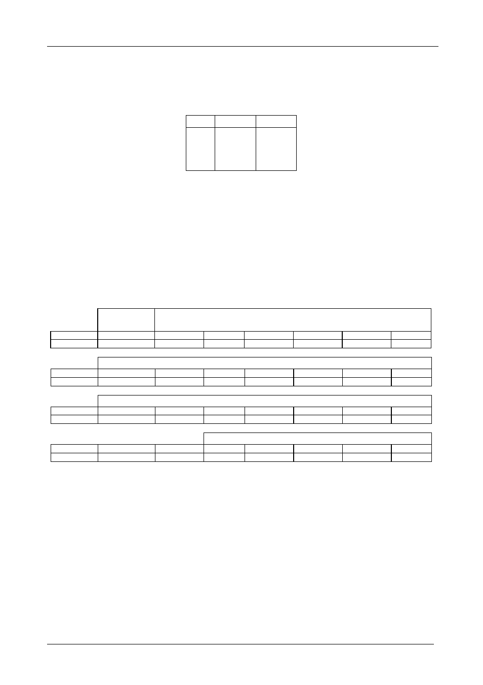
Table 4 lists the Hex values for switching on the
VS-201YC.
Table 4: Hex Codes
IN 1
IN 2
OUT
2
1
9 VS-201YC Communication Protocol
The
VS-201YC is compatible with Kramer’s Protocol 2000 (version 0.46)
(below). This RS-232/RS-485 communication protocol uses four bytes of
information as defined below. For RS-232, a null-modem connection between
the machine and controller is used. The default data rate is 9600 baud, with no
parity, 8 data bits and 1 stop bit.
Table 5: Protocol Definitions
MSB
LSB
DESTI-
NATION
INSTRUCTION
0
D
N5
N4
N3
N2
N1
N0
7
6
5
4
3
2
1
0
1st byte
INPUT
1
I6
I5
I4
I3
I2
I1
I0
7
6
5
4
3
2
1
0
2nd byte
OUTPUT
1
O6
O5
O4
O3
O2
O1
O0
7
6
5
4
3
2
1
0
3rd byte
MACHINE NUMBER
1
OVR
X
M4
M3
M2
M1
M0
7
6
5
4
3
2
1
0
4th byte
1
st
BYTE:
Bit 7 – Defined as 0.
D – “DESTINATION”:
0 - for sending information to the switchers (from the PC);
1 - for sending to the PC (from the switcher).
N5…N0 – “INSTRUCTION”
The function that is to be performed by the switcher(s) is defined by the INSTRUCTION (6 bits). Similarly, if a function is
performed via the machine’s keyboard, then these bits are set with the INSTRUCTION NO., which was performed. The
instruction codes are defined according to the table below (INSTRUCTION NO. is the value to be set for N5…N0).
2
nd
BYTE:
Bit 7 – Defined as 1.
I6…I0 – “INPUT”.
When switching (ie. instruction codes 1 and 2), the INPUT (7 bits) is set as the input number which is to be switched.
Similarly, if switching is done via the machine’s front-panel, then these bits are set with the INPUT NUMBER which was
switched. For other operations, these bits are defined according to the table.
3
rd
BYTE:
Bit 7 – Defined as 1.
O6…O0 – “OUTPUT”.