Kramer Electronics VP-728 User Manual
Page 13
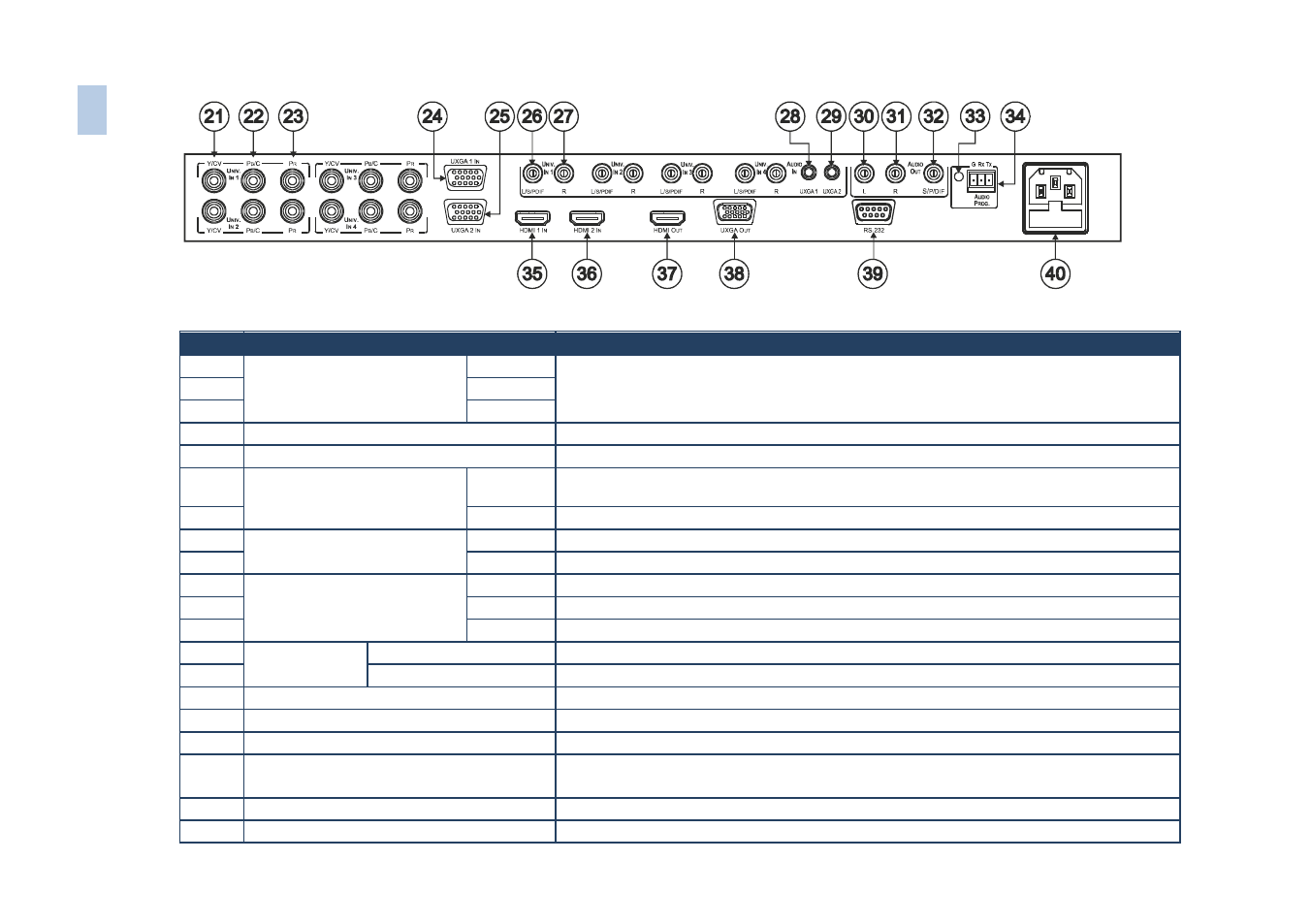
Figure 2: VP-728 Presentation Switcher/Scaler Rear Panel
#
Feature
Function
21
UNIV. IN RCA Connectors
(from 1 to 4)
Y/CV
Connects to the video acceptor which can be either composite video (Y/CV), s-Video (Y/CV,
P
B
/C ) or component video (Y/CV, P
B
/C, P
R
)
22
P
B
/C
23
P
R
24
UXGA 1 IN 15-pin HD Connector
Connects to the UXGA (analog interface) graphics source 1
25
UXGA 2 IN 15-pin HD Connector
Connects to the UXGA (analog interface) graphics source 2
26
AUDIO IN UNIV. IN RCA
Connectors (from 1 to 4)
L/S/PDIF
Connects to the left unbalanced stereo analog audio source. Alternatively, connect to a digital
audio source
27
R
Connects to the right unbalanced stereo analog audio source
28
AUDIO IN 3.5 Mini Jack
UXGA 1
Connects to the unbalanced stereo analog audio source 1
29
UXGA 2
Connects to the unbalanced stereo analog audio source 2
30
AUDIO OUT RCA Connectors
L
Connects to the left channel of the unbalanced stereo analog audio acceptor
31
R
Connects to the right channel of the unbalanced stereo analog audio acceptor
32
S/PDIF
Connects to a digital audio acceptor
33
AUDIO PROG
Program Button
Push to upgrade to the latest Kramer audio firmware. Release for normal operation
34
Terminal Block Connector
Connects to a PC for audio firmware upgrade
35
HDMI 1 IN Connector
Connects to the HDMI 1 source
36
HDMI 2 IN Connector
Connects to the HDMI 2 source
37
HDMI OUT Connector
Connects to the HDMI acceptor
38
UXGA OUT 15-pin HD Connector
Connects to the video acceptor that displays the scaled output.
In the default HDTV mode, the signal is transmitted via 3 pins: PIN 1 is Pr, PIN 2 is Y, PIN 3 Pb
39
RS-232 9-pin D-sub Connector
Connects to a PC or serial controller
40
Power Connector with Fuse
AC connector for connecting power to the unit
8
VP
-72
8 –
O
ve
rvi
ew