1 connecting the remote step-in switch and led, Connecting the remote step-in switch and led, Figure 4: remote step-in switch and led wiring – Kramer Electronics SID-X3N User Manual
Page 12
8
SID-X3N - Connecting the SID-X3N
3. Connect the AUDIO OUT 3.5mm mini jack to the unbalanced, stereo audio
acceptor, (for example, a power amplifier with speakers).
4. Connect the HDMI OUT connector to a compatible switcher, (for example,
VS-62H or KW-11T).
5. Connect the REMOTE STEP-IN 3-way terminal block to a contact closure
switch and LED, (see
6. Connect the REMOTE SELECT 3-way terminal block to a momentary
contact closure switch and LEDs, (see
7. Connect the LED ANODES 5-way terminal block to the remote input
indicator LEDs, (see
8. If required, connect a device requiring a 5V DC power supply, (for example,
the KW-11T, not shown in
Figure 3
).
9. Connect the power adapter to the SID-X3N and to the mains power, (not
shown in
Figure 3
).
Note: All LED supplies include a current limiting resistor and are designed to work
with any standard LED.
5.1
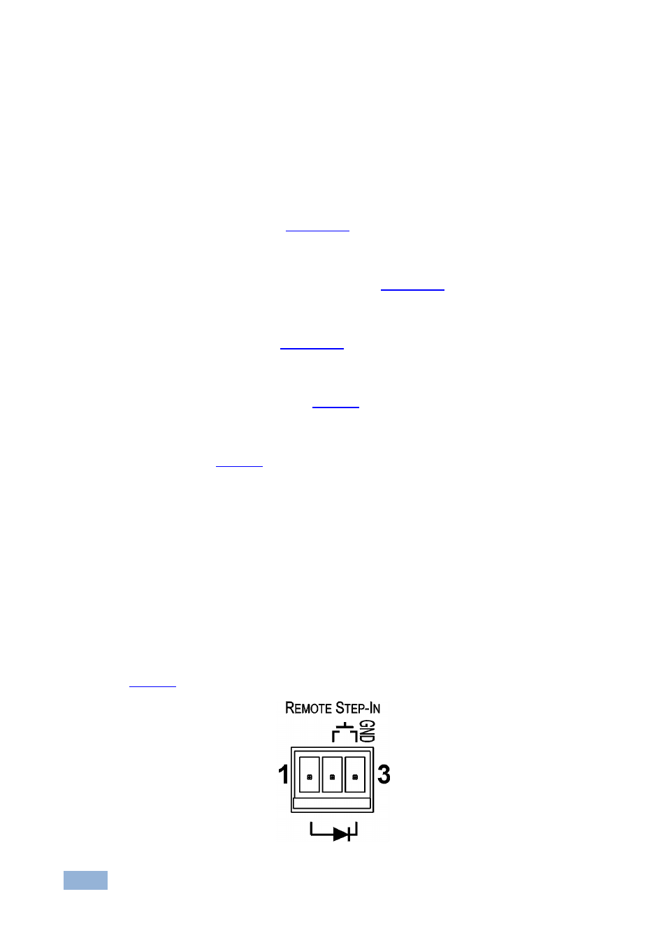
Connecting the Remote Step-In Switch and LED
You can connect a remote, contact closure step-in switch to take control of the
input of the attached switcher, as well as a remote step-in LED to the REMOTE
STEP-IN terminal block on the rear panel of the SID-X3N.
illustrates the connections from the terminal block to the switch and LED.
Figure 4: Remote Step-In Switch and LED Wiring