Figure 2: sid-x3n step-in commander rear panel – Kramer Electronics SID-X3N User Manual
Page 10
6
SID-X3N - Defining the SID-X3N Step-in Commander
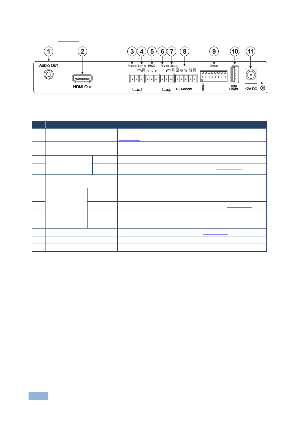
defines the rear panel of the SID-X3N.
Figure 2: SID-X3N Step-in Commander Rear Panel
#
Feature
Function
1
AUDIO OUT 3.5mm Mini Jack
Connect to an unbalanced, stereo audio acceptor, (see
Section
2
HDMI OUT Connector
Connect to a compatible switcher, for example, VS-62H using an
HDMI cable
3
REMOTE STEP-IN
3-pin Terminal
Block
LED
Connect to the anode of the remote Step-In LED indicator
4
Switch
Connect to the remote, Step-In switch, (see
Section
5
PROG RS-232 3-pin Terminal
Block
Connect to the PC via RS-232 to perform a firmware upgrade
6
REMOTE
SELECT 8-pin
Terminal Block
LED
Connect to the anode of the remote Input Select LED indicator,
(see
Section
7
Switch
Connect to the remote, Input Select switch, (see
Section
8
LED HDMI,
DP, DVI
and UXGA
Connect to the anodes of the remote input indicators
(see
Section
9
OPTION 8-way DIP-switch
Used to set the device behavior, (see
Section
10
USB POWER Connector
Provides 5V DC power to a device
11
12V DC Power Connector
Connect to supplied power adapter, center pin positive