2 wiring the rs-232 connector, Wiring the cat 5 line in/line out rj-45 connectors, Wiring the rs-232 connector – Kramer Electronics TP-210A User Manual
Page 12: Figure 4: cat 5 pinout, Figure 5: rs-232 pinout connection, Table 3: cat 5 pinout, Tp-210a to controlled unit, Connecting the tp-210a, Table 3: cat 5 pinout figure 4: cat 5 pinout
KRAMER: SIMPLE CREATIVE TECHNOLOGY
Connecting the TP-210A
10
6.1
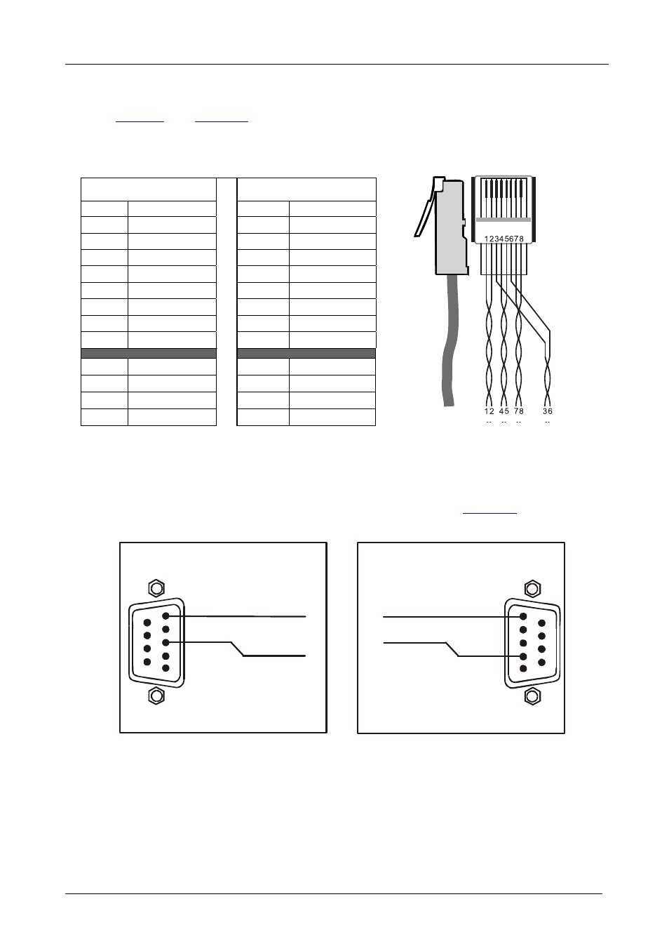
Wiring the CAT 5 LINE IN/LINE OUT RJ-45 Connectors
define the UTP CAT 5 PINOUT, using a straight pin
to pin cable with RJ-45 connectors:
Table 3: CAT 5 PINOUT
Figure 4: CAT 5 PINOUT
EIA /TIA 568A
EIA /TIA 568B
PIN
Wire Color
PIN
Wire Color
1 Green/White
1 Orange/White
2 Green
2 Orange
3 Orange/White
3 Green/White
4 Blue
4 Blue
5 Blue/White
5 Blue/White
6 Orange
6 Green
7 Brown/White
7 Brown/White
8 Brown
8 Brown
Pair 1
4 and 5
Pair 1
4 and 5
Pair 2
3 and 6
Pair 2
1 and 2
Pair 3
1 and 2
Pair 3
3 and 6
Pair 4
7 and 8
Pair 4
7 and 8
6.2
Wiring the RS-232 Connector
Prepare an RS-232 cable with a 9-pin D-sub connector at one end, and a 2-pin
terminal block connector at the other end, as defined in
:
Figure 5: RS-232 PINOUT Connection
Rx
PIN 5 Connected to G
PIN 3 Connected to Rx
1
2
3
4
5
6
7
8
9
PC (9-pin D-sub)
9-pin D-sub
RS-232 to TP-210A
G
G
PIN 5
Connected to
Tx Connected to PIN 2
Tx
G
1
2
3
4
5
6
7
8
9
TP-210A to Controlled Unit