Kramer Electronics VM-1042 User Manual
Page 13
KRAMER ELECTRONICS LTD.
11
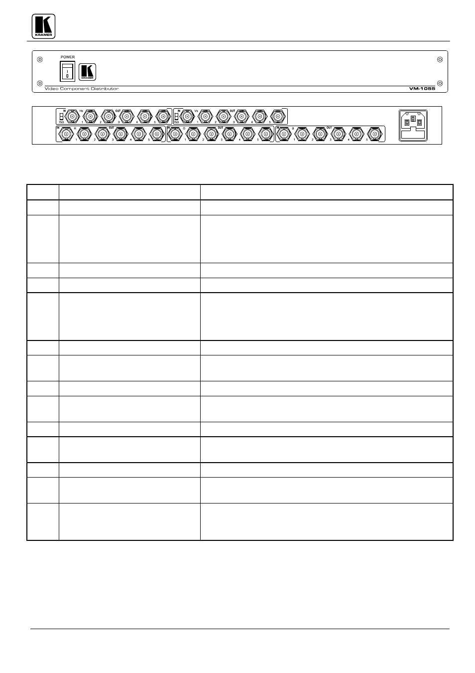
Figure 6: VM-1055 Front/Rear Panel Features
Table 9: VM-1055 Front/Rear Panel Features
No.
Feature
Function
1.
Power switch
Illuminated switch: Supplies power to the unit.
2.
75 switch
Selects
“ 75 “ or “ HI-z” impedance for Hs Channel. When at
the
"75 " position, the signal applied to the connector
should be analog video or sync signal. When in the
“ HI-z”
position a TTL level sync signal may be used.
3.
IN Hs BNC connector
Hs Channel video input (horizontal sync).
4.
OUT Hs 1- 5 BNC connectors
Hs Channel amplified and buffered video outputs.
5.
75 switch
Selects
“ 75 “ or “ HI-z” impedance for Vs Channel. When at
the
"75 " position, the signal applied to the connector
should be analog video or sync signal. When in the
“ HI-z”
position a TTL level sync signal may be used.
6.
IN Vs BNC connector
Vs Channel video input(vertical sync).
7.
OUT Vs 1- 5 BNC connectors
Vs Channel amplified and buffered video outputs that are
identical to each other and to the input.
8.
IN R BNC connector
R Channel video input.
9.
OUT R 1-5 impedance for Vs
Channel.
R Channel amplified and buffered video outputs that are
identical to each other and to the input.
10.
IN G BNC connector
G Channel video input.
11.
OUT G 1-5 BNC connectors
G Channel amplified and buffered video outputs that are
identical to each other and to the input.
12.
IN B BNC connector
B Channel video input.
13.
OUT B 1-5 BNC connectors
B Channel amplified and buffered video outputs that are
identical to each other and to the input.
14.
Power Connector
A 3-prong AC connector allows power to be supplied to the
unit. Directly underneath this connector, a fuse holder houses
the appropriate fuse.