Figure 2 – Kramer Electronics VM-1055 User Manual
Page 8
6
VM-1010, VM-1021, VN-1055, VM-54 - Your VM-1010
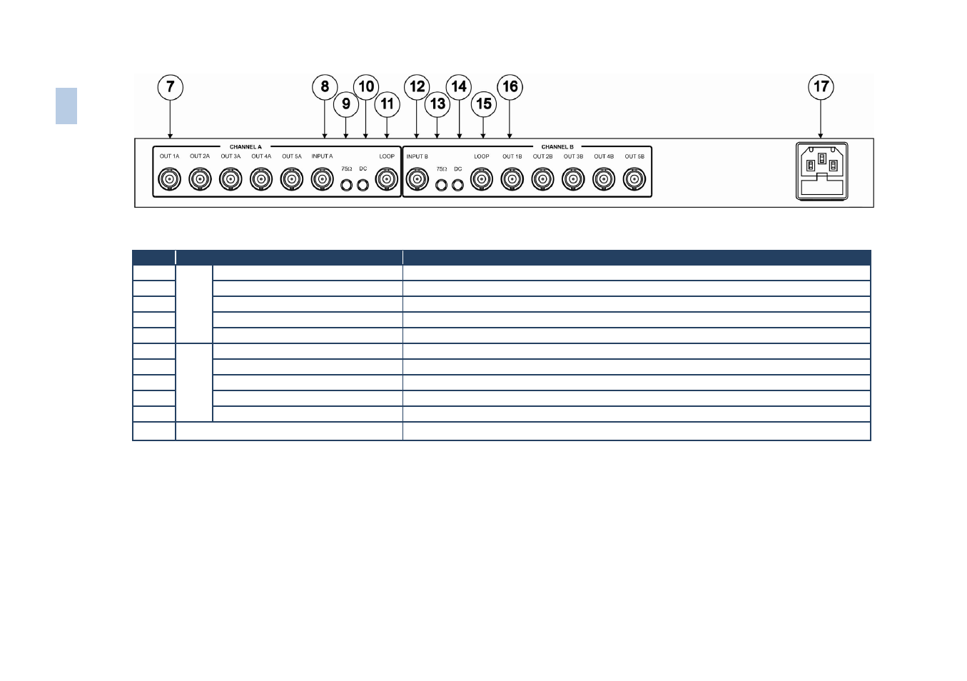
Figure 2: VM-1010 Programmable Video Distributor Rear Panel
#
Feature
Function
7
CHA
NNE
L
A
OUT BNC Connectors (1A-5A)
5 amplified and buffered video outputs
8
INPUT A BNC Connector
Connects to a composite/component/YC/analog sync video source A
9 75Ω Button
Selects "75Ω" or "HI-z" impedance (for looping select "Hi-z")
10
DC Button
Selects DC coupling when pushed
11
LOOP BNC Connector
Provides video looping capability to increase number of outputs
12
CHA
NNE
L
B
INPUT B BNC Connector
Connects to a composite/component/YC/analog sync video source B
13 75Ω Button
Selects "75Ω" or "HI-z" impedance (for looping select Hi-z)
14
DC Button
Selects DC coupling when pushed
15
LOOP BNC Connector
Provides video looping capability to increase number of outputs
16
OUT BNC Connectors (1B-5B)
5 amplified and buffered video outputs.
17
Power Connector
AC connector and fuse enabling power supply to the unit
6
VM-1010, VM-1021
, V
N
-10
55, VM-54
– The
VM-101
0 P
rogrammable
V
ide
o Dist
ributor