2 pneumatic installation, 5 commissioning, 6 operation – Festo Модули перемещения HSW User Manual
Page 4: 7 maintenance and care, 8 disassembly and repair, 9 accessories, 10 troubleshooting, 11 technical data
4.2 Pneumatic installation
• Use GRLA one-way flow control valves for
setting the swivel speed.
These are screwed directly into the com-
pressed air supply ports
2 (Fig. 7).
Fig. 7
2
2
During the swivel procedure, the following relationship between swivel speed and
flow control exists.
Factor
Supply air flow
control
Exhaust air flow
control
Supply and
exhaust air flow
control
Swivel speed
Increasing
Decreasing
Approach method
constant
Swivel time
Short
Long
Long
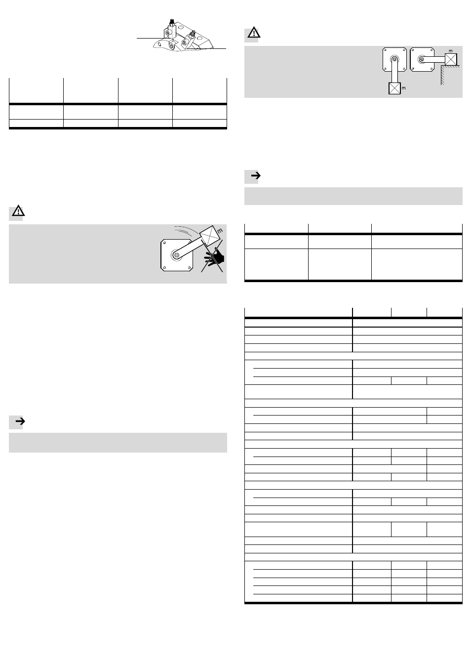
Fig. 8
For eccentric loads:
• Check whether HGL controlled non-return valves or a VZS air reservoir are ne-
cessary.
In this way you can prevent the useful load from sliding down suddenly if there
is a sudden pressure drop.
5
Commissioning
Warning
Danger of injury from rotating loads.
• Make sure that the DSM is set into motion only
with protective devices.
• Make sure that in the swivel angle of the DSM
– nobody can reach in
– no objects can enter (e.g. by means of an indi-
vidual protective guard).
1. Turn both upstream one-way flow control valves
– at first completely closed
– then open them again approximately one turn.
2. Make sure that the operating conditions lie within the permissible ranges.
3. Pressurize the drive optionally in one of the following ways:
–
slowly Pressurisation of one side
– simultaneous pressurisation of both sides with subsequent venting of one
side.
4. Start a test run.
5. During a test run check whether the following settings on the DSM need to be
modified:
– the swivel angle (only in combination with stop kit KSM-...)
– the swivel speed.
6. Slowly screw open the one-way flow control valves until the desired swivel
speed is set. The internal rotary vane should reach the end position safely, but
not strike hard against it.
Note
If the impact is too hard, it will cause rebounding out of the end position and a
reduction of the service life.
If the rotary vane audibly strikes hard:
7. Interrupt the test run.
Causes of hard impact may be:
– mass moment of inertia of the moving load too high
– swivel speed too high
– no compressed air cushion on the exhaust side.
8. Make sure you remedy the above-mentioned causes.
9. Repeat the test run.
When all necessary corrections have been made:
10. End the test run.
6
Operation
For several uninterrupted swivel cycles:
• Make sure that the maximum permissible swivel frequency is observed
(
Technical data).
Otherwise, the operational reliability will be impaired by excessive temperature
rise.
7
Maintenance and care
If the device is dirty:
• Clean the DSM with a soft cloth.
All non-abrasive cleaning agents are permissible (e.g. warm soap suds up to
+60 °C).
8
Disassembly and repair
For eccentric masses on the lever arm:
Warning
Risk of injury from masses that slide down sud-
denly if there is a drop in pressure.
• Make sure that the load has reached a stable
position before venting (e.g. the lowest
point).
Recommendation:
• Return the product to our repair service for overhaul. This way the fine tuning
and tests that are required will be taken into particular consideration.
Information about spare parts and accessories can be found at:
www.festo.com/spareparts.
9
Accessories
Note
• Please select the corresponding accessories from our catalogue
(
www.festo.com/catalogue).
10
Troubleshooting
Malfunction
Possible cause
Remedy
Uneven movement
Flow control valves
inserted incorrectly
– Check the flow control valve
functions (exhaust air flow control)
– Hard impact at the end
position
– Drive shaft does not
remain in the end
position
Residual energy too high
– Select lower swivel speed
– Use external shock absorbers
– Move only against residual air
cushion on the exhaust side
– Select lighter loads of the useful load
Fig. 9
11
Technical data
Size
6
8
10
Pneumatic connection
M3
Design
Swivel module with rotary vane
Type of mounting
With female thread
Mounting position
Any
Max. swivel frequency at 6 bar
DSM(-T)-…-90
[Hz]
3
DSM(-T)-…-180
[Hz]
3
DSM(-T)-…-240
[Hz]
–
–
2
Operating medium
Compressed air in accordance with
ISO 8573-1:2010 [7:4:4]
Min. operating pressure
DSM
[bar]
3.5
2.5
DSM-T
[bar]
4
3.5
Max. operating pressure
[bar]
8
Ambient temperature
[°C]
0 … +60
Theoretical torque at 6 bar
DSM
[Nm]
0.15
0.35
0.85
DSM-T
[Nm]
0.3
0.7
1.7
Permissible stop radius r
min
[mm]
10
13
Permissible stop force F
max
[N]
15
30
60
Max. permissible force on the drive shaft
Axial force F
X
[N]
10
Radial force F
Z
[N]
15
20
30
Note on materials
Free of copper and PTFE
Material information and product weight
www.festo.com/catalogue
Permissible mass moment of
inertia
1)
[10
–5
kg m
2
]
0.5
1.0
2.0
Cushioning
Flexible cushioning at both ends
Cushioning angle
[°]
0.5
Swivel angle
2)
DSM(-T)-…-90
[°]
90
+ 5 3)
90
+ 5
90
+ 5
DSM(-T)-…-180
[°]
0 … 180
+ 5 3)
0 … 180
+ 5
0 … 180
+ 5
DSM(-T)-…-240
[°]
–
–
0 … 240
+ 5
DSM(-T)-…-180-…-FF-…
[°]
0 … 180
+ 5 3) 4)
0 … 180
+ 5 4)
–
DSM(-T)-…-240-…-FF-…
[°]
–
–
0 … 200
+ 5 4)
1)
Unthrottled.
2)
Adjustment of swivel angle at DSM(-T)-… only with accessories.
3)
Only adjustable symmetrical to the centre.
4)
Precision adjustment (–5
…
+1°) via adjusting screw.
Fig. 10