SawStop T-Glide Fence System User Manual
Page 10
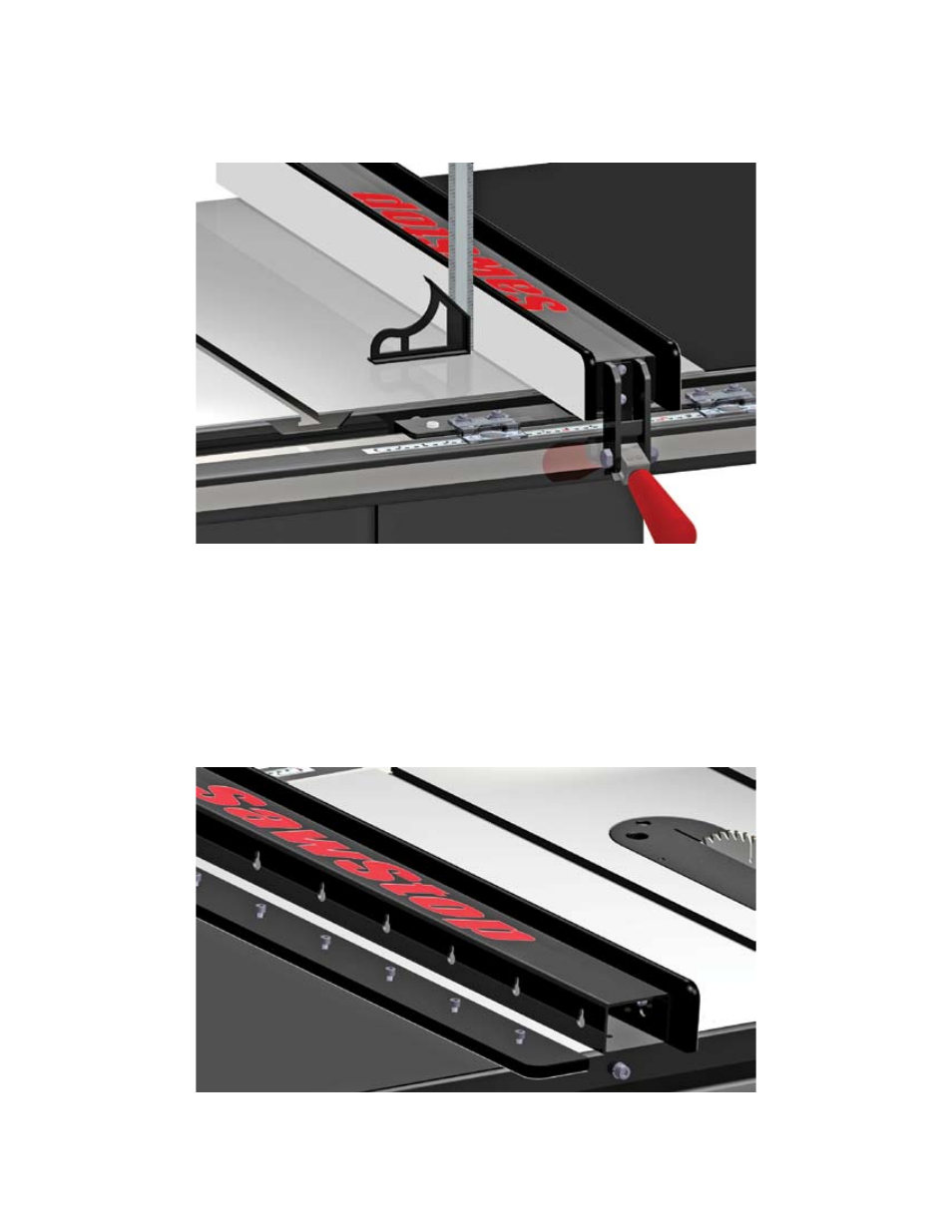
Place a combination square on the table top and against the left face plate. See Fig. 13. Use a 6 mm hex key
to adjust the leveling screws as necessary until the face plate is parallel to the vertical edge of the combination
square.
If necessary, you can adjust both of the plastic set screws to ensure the position indicator lenses are close to,
but not touching, the main tube or rulers.
The last step is to set the spacing between the bottom of each face plate and the table. The face plates are
held in place by a series of screws threaded into nuts embedded in the face plates. The heads of the screws
fit into key-hole slots in the sides of the fence. See Fig. 14.
page 8
Fig. 14
Fig. 13