D-sub 9 pin female rs-232 pin-out, Fig. 9.3 – Ashly VCM-88 User Manual
Page 11
11
Operating Manual - VCM-88, VCM-88E, RD-8, RW-8 Level Controllers
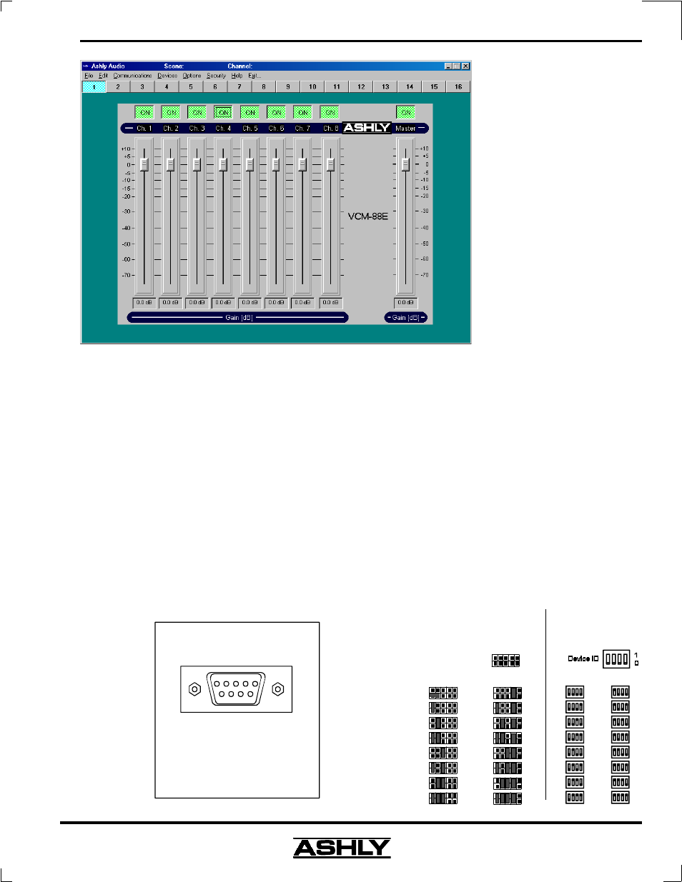
To use the VCM-88 with Protea Software, internal
data jumpers (see fig. 9.2) must be placed in the RS-232
position on the printed circuit board.
On the VCM-88E, the Standard protocol selection
is used for Ashly RD-8, RW-8, AMX, and Crestron. To
control the VCM-88E with Protea System Software, select
the Protea Software protocol on the back-panel DIP
switches.
The RS-232 Input connector to a VCM-88(E) is a
D-Sub 9 pin female, and connects to an unused Com port
on a PC. See fig. 9.4 for custom RS-232 wiring. Protea
System Software allows Com Port assignment (1-16) in its
setup menu. If the only available port on a PC is a USB
port, a USB to RS-232 converter can be purchased from
computer suppliers. Protea System Software is available
free of charge on the Ashly website
9.5 MIDI Implementation
Both the VCM-88 and the
VCM-88E can be fully imple-
mented in a MIDI system as a
slave unit, that is, able to receive
data without being able to gener-
ate new data. On the VCM-88, the
MIDI Thru jack is a buffered re-
flection of the MIDI input, and is
used to connect to other MIDI de-
vices in the network. On the VCM-
88E, use the Slave Data In and Out
to connect to a MIDI controller.
The quality and accuracy of MIDI
control is limited only by the qual-
ity of the MIDI Master device.
To use the VCM-88 in a
MIDI network, two circuit board
jumpers must be placed in the
MIDI position (see fig. 9.2) to se-
lect the MIDI communications
protocol. To use the VCM-88E in a MIDI network, set the
back panel Protocol DIP switch to the MIDI configuration.
Set the VCM-88 to the desired MIDI Channel
(VCM-88 device 1-16) using the Bank ID Select jumpers
found on the circuit board (see fig. 9.5). Device 1 equals
MIDI channel 1, device 2 equals MIDI channels 2, and so
on, up to device 16.
Set the VCM-88E to the desired MIDI Channel by
using the Device ID DIP switches on the back panel. The
VCM-88E Slave Data signals, which are located on a 6-pin
euroblock style connector, may be used to interface other
VCM-88E units for software or MIDI control. The Slave
Data jack may also be used to interface Ashly Protea prod-
ucts, via their MIDI In/Out jacks, (see pin compatibility
Fig. 9.4
Fig. 9.5
D-Sub 9 Pin Female
RS-232 Pin-Out
1
2
3
4
5
9
8
7
6
Pin # RS-23 2 DCE Name
1
2
3
4
5
6
7
8
9
Not C onnected
Transm itted Data
Received Data
Data Terminal Ready (tied to pin 6 )
Ground
Data Set Ready (tied to pin 4)
Not C onnected
Not C onnected
Not C onnected
0
VCM-88
Internal
Device ID
(MIDI Channel)
Jumper Select
1 2 3 4
1
2
3
4
5
6
7
8
9
10
11
12
13
14
15
16
* PCB May Say
"Bank Select"
(default)
VCM-88E
Back Panel
Device ID
(MIDI Channel)
DIP Switch Select
1
2
3
4
5
6
7
8
9
10
11
12
13
14
15
16
(default)
Fig. 9.3