Warning, Electrical wiring – Comfort-Aire FMG****F1E Series User Manual
Page 8
8
ELECTRICAL WIRING
WARNING:
ELECTRICAL SHOCK, FIRE OR EXPLOSION
HAZARD
Failure to follow safety warnings exactly could
result in serious injury or property damage.
Improper servicing could result in dangerous
operation, serious injury, death or property
damage.
• Before servicing, disconnect all electrical power
to air handler.
• When servicing controls, label all wires prior
to disconnecting. Reconnect wires correctly.
• Verify proper operation after servicing.
• Electrical connections must be in compliance with
all applicable local codes and ordinances, and with
the current revision of the National Electric Code
(ANSI/NFPA 70).
• For Canadian installations, the electrical connections
and grounding shall comply with the current Canadian
Electrical Code (CSA C22.1 and/or local codes).
Line Voltage
•
An electrical disconnect must be located within sight
of and readily accessible to the unit. This switch shall
be capable of electrically de-energizing the outdoor unit.
See unit data label for proper incoming field wiring. Any
other wiring methods must be acceptable to authority
having jurisdiction.
• It is recommended that the line voltage to the unit be
supplied from a dedicated branch circuit containing the
correct fuse or circuit breaker for the unit.
• Overcurrent protection must be provided at the branch
circuit distribution panel and sized as shown on the unit
rating label and according to applicable local codes. See
the unit rating plate and Table 2 for maximum circuit
ampacity and maximum overcurrent protection limits.
• Refer to the unit wiring label for proper high and low
voltage wiring.
• Use only copper wire for the line voltage power supply
to this unit. Use proper code agency listed conduit and
a conduit connector for connecting the supply wires to
the unit.
• If replacing any of the original wires supplied with the
unit, the replacement wire must be copper wire consisting
of the same gauge and temperature rating.
• Provide power supply for the unit in accordance with
the unit wiring diagram, and the unit rating plate. The
installer should become familiar with the wiring diagram/
schematic before making any electrical connections to
the unit. See Figures 5 - 8 (pages 14 - 17).
• All 208/230 Volt units are shipped from the factory wired
for 240 volt operation. For 208V operation, remove the
lead from the transformer terminal marked 240V and
connect it to the terminal marked 208V.
Grounding
WARNING:
The unit cabinet must have an uninterrupted or
unbroken electrical ground to minimize personal
injury if an electrical fault should occur. Do not
use gas piping as an electrical ground!
This unit must be electrically grounded in accordance
with local codes or, in the absence of local codes, with
the National Electrical Code (ANSI/NFPA 70) or the CSA
C22.1 Electrical Code. Use the grounding lug provided in
the control box for grounding the unit.
Thermostat Connections
• Thermostat connections shall be in accordance with the
instructions supplied with the thermostat and the indoor
equipment. The low voltage wires must be properly
connected to the units low voltage terminal block.
• A single stage thermostat is used with this equipment
and must operate in conjunction with any installed
accessories. Typical AC and air handler hookups are
shown in Figure 4.
• The thermostat should be mounted about 5 feet above the
floor on an inside wall. DO NOT install the thermostat on
an outside wall or any other location where its operation
may be adversely affected by radiant heat from fireplaces,
sunlight, or lighting fixtures, and convective heat from
warm air registers or electrical appliances. Refer to the
thermostat manufacturer’s instruction sheet for detailed
mounting and installation information.
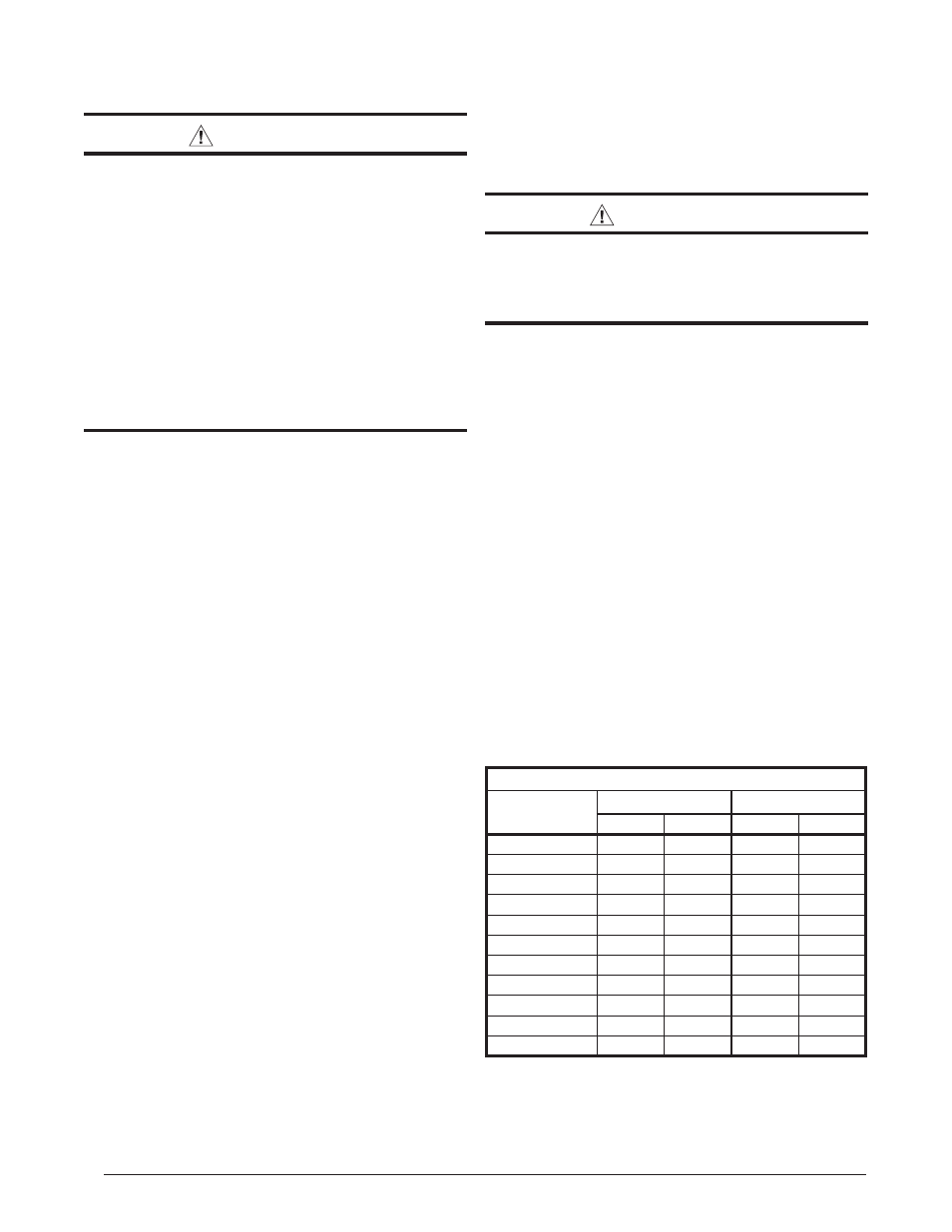
Minimum Circuit Ampacity & Maximum Overcurrent Protection
Model #
240VAC, 50 & 60Hz
208VAC, 50 & 60Hz
MCA
MOP
MCA
MOP
FMG1805F1E
26.1
30
22.8
25
FMG1808F1E
40.2
50
34.8
40
FMG2405F1E
26.5
30
23.1
30
FMG2408F1E
40.6
50
35.1
40
FMG2410F1E
51.5
60
44.8
50
FMG3005F1E
26.6
30
23.2
30
FMG3008F1E
40.8
50
35.2
40
FMG3010F1E
51.6
60
44.9
50
FMG3605F1E
29.2
30
25.9
30
FMG3608F1E
43.3
50
37.9
40
FMG3610F1E
54.2
60
47.5
50
MCA = Minimum Circuit Ampacity
MOP = Maximum Over-Current Protection
Table 2. Electrical Rating Data