Figures & tables, Table 5. fmg specifications, Figure 4. physical dimensions – Comfort-Aire FMG****F1E Series User Manual
Page 12
12
“B”
18 5/8
1
1
Ø3/8" K.O.
3/4
15
1 1/2
1 1/2
2 5/8
6 1/4
10 1/2
19
10 1/2
Drain
Knockout
Optional
Refrigerant
Line Entry
1 5/8
20 1/2
1 5/8
Liquid Line
2 1/8
Suction
Line
1
7/8
1 1/4
1
1 7/8
3/4
Ø3/8" Low
Voltage
Optional
Refrigerant
Line Entry
Drain
Knockout
Ø1 1/8" K.O.
Power Entry
Ø1 1/8" K.O.
Power Entry
1 5/8
FRONT VIEW
RIGHT
SIDE
LEFT
SIDE
BOTTOM
VIEW
3/4
TOP
VIEW
Primary & Secondary
Drain Connections
“A”
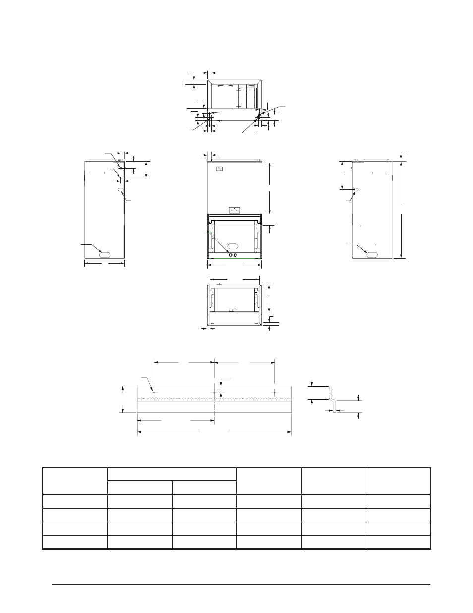
Table 5. FMG Specifications
MODEL
REFRIGERANT CONNECTIONS
SUPPLY AIR
DUCT DIMENSION
A
B
SUCTION DIA.
LIQUID DIA.
FMG18(****)F1E
3/4
3/8
9 x 17 1/4
36 3/8
9 1/2
FMG24(****)F1E
3/4
3/8
9 x 17 1/4
36 3/8
9 1/2
FMG30(****)F1E
3/4
3/8
9 x 17 1/4
43 1/2
9 1/2
FMG36(****)F1E
3/4
3/8
15 x 17 1/4
43 1/2
15 1/2
Figure 4. Physical Dimensions
FIGURES & TABLES
8”
8”
7/8”
20 3/8”
10 3/16”
Ø
7/32”
(3 places)
3 1/2”
1 3/4”
1 3/4”
.07”
MTG BRACKET