Caution – Comfort-Aire FMG****F1E Series User Manual
Page 7
7
CAUTION:
It is recommended that a wet rag be wrapped
around the suction line before applying heat.
Failure to keep components cool during brazing
may result in structural damage, premature
equipment failure, or possible personal injury.
3. Braze the individual connections with dry nitrogen flowing
through the joints. This will prevent internal oxidation
and scaling from occurring.
4. Wrap the refrigerant lines with pressure sensitive
neoprene or other suitable material especially where
the lines enter the opening in the sheet metal.
5. Evacuate the system of moisture and non-condensables
to prevent low efficiency operation or damage to the
unit. The suggested range of evacuation is 350 - 500
microns.
6. Charge the system with refrigerant. Refer to the
outdoor unit installation manual for additional charging
instructions.
7. Check the system for leaks, including the lineset and
the brazed joints.
8. Properly dispose of all removed parts.
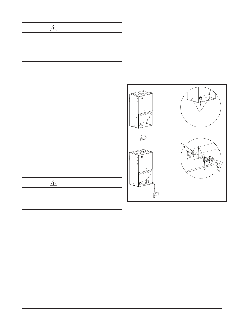
Condensate Drainage
The drain pan that is supplied with this air handler contains
a primary and secondary drain fitting. The condensate is
drained from the unit through two 3/4” male pipe fittings
located on the front side of the unit as shown in Figure
2 (page 8).
CAUTION:
The air handler must be level to ensure proper
condensate drainage. An unlevel installation
may result in structural damage, premature
equipment failure, or possible personal injury.
• The method for disposing of condensate varies according
to local codes. Consult your local code or authority
having jurisdiction.
• The drain lines can be routed out the bottom, left or right
side of the air handler, but must maintain a downward
slope to ensure proper condensate drainage. If the
bottom access panel is moved to the front (for bottom
return air), the condensate drain tubes must be routed
thru one of the side openings. DO NOT route the
condensate drain tubes thru the front panel.
• Drain pan MUST be drained with field supplied tubing and
looped to form a trap. Failure to install a trap could result
in condensation overflowing the drain pan, resulting in
substantial water damage to surrounding area. Both
drains must be trapped separately. See Figure 2.
• It is recommended that both drain tubes have a minimum
internal diameter of 1/2” and be separately routed to
a suitable drain, avoiding sharp bends and pinching of
the lines. Refer to local codes and restrictions for proper
condensate disposal requirements.
• Both adapters should be made of PVC or similar
material and contain a rubber washer. Hand tightened
the adapters to the drain pan. DO NOT use pliers or
any other tools.
Overtightening may crack the drain
pan and cause condensate to leak.
• During system checkout, inspect the drain line and
connections to verify proper condensate drainage.
Rubber
Washers
Side Drainage
Bottom Drainage
1/2” I.D.
Drain Tubes
3/4” NPT Adapters
w/ 1/2” Hose Barb
NOTES:
1. Field supplied drain lines must be looped to form a trap.
2. Drain lines must be routed to the outside of the cabinet.
3. Avoid sharp bends and pinching of the tubing.
Knockouts for condensate drain tubes
(
bottom, left, or right side of unit
Primary & Secondary
Drain Locations
See Notes
See Notes
Figure 2. Condensate Drainage