Wiring dia gram, Wall mount air handler (5kw/036), Contr ol bo ard – Comfort-Aire FMG****F1E Series User Manual
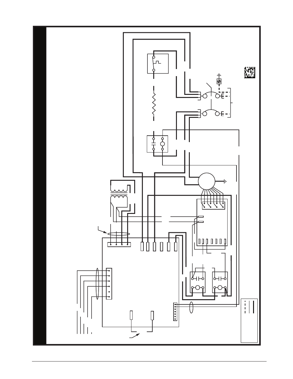
Page 16: T-bo ard, Figure 7. wiring diagram for 3 ton units (5kw)
16
711243
0
0812
FIELD
WIRIN
G
LEGEND
:
LO
W
VO
LT
AG
E
HIGH
VO
LT
AG
E
WIRING DIA
GRAM
W
all Mount Air Handler (5KW/036)
3.
The transf
ormer ma
y ha
ve a dual v
oltage primary
tap.
Match the tap position with the suppl
y
vo
ltage used.
4.
If the Internal wiring is replaced,
use onl
y 105°C copper
wire of the same gauge
.
NO
TES:
1.
The blo
wer motor speed tap connection ma
y not be as
shown. See the Installation Instructions.
2.
Disconnect all po
wer bef
ore servicing.
Remar
ques
1.
Le connecteur de vitesse du moteur du ventilateur
peut différer de l’illustration
. Consultez les
Instructions d’installation.
2.
Débranchez toutes les sour
ces d’alimentation
av
ant
l’entretien.
3.
Le transf
ormateur peut
av
oir un
ro
binet principal à
double tension.
Agencez la position du
ro
binet au
type de tension de l’installation.
4.
Si le câblage interne est remplacé,
utilisez seulement
un fil de cuivre 105° C du même gabarit
.
CIRCUIT
BREAKER
LIMI
T
ELEMENT RELA
Y
ELEMENT
SUPPL
Y
VO
LT
AG
E
CONTR
OL
BO
ARD
R
C
L2
L1
HEA
T
COOL
EA
C
L1
L2
Y
W
GC
R
TRANSFORMER
24V
230V
EC
M
MO
TO
R
COM1
U1
U2
T-BO
ARD
RELA
Y
1
RELA
Y
2
HEA
TER
ORANGE
BLA
CK
WHITE
GRA
Y
COM
NO
2
1
4
3
2
1
4
3
M1
M2
M3
M4
M5
HUM
RED
BLA
CK
WHIT
E
GRA
Y
YELLO
W
WHIT
E
GRA
Y
RED
GREEN
RED
BL
AC
K
BLA
CK
WHITE
RED
BLA
CK
RED
GRAY
BLA
CK
HARNESS
HARNESS
HARNESS
RED
WHITE
RED
GRA
Y
RED
BLACK
BLA
CK
WHITE
BL
WDTC
R
BLAC
K
IF BO
ARD
EQUIPPED
WITH
BL
WDTC
TERMINAL
Figure 7. Wiring Diagram for 3 Ton Units (5kW)