Bell & Gossett P81630F Series VSCS Base Mounted Centrifugal Pumps User Manual
Page 9
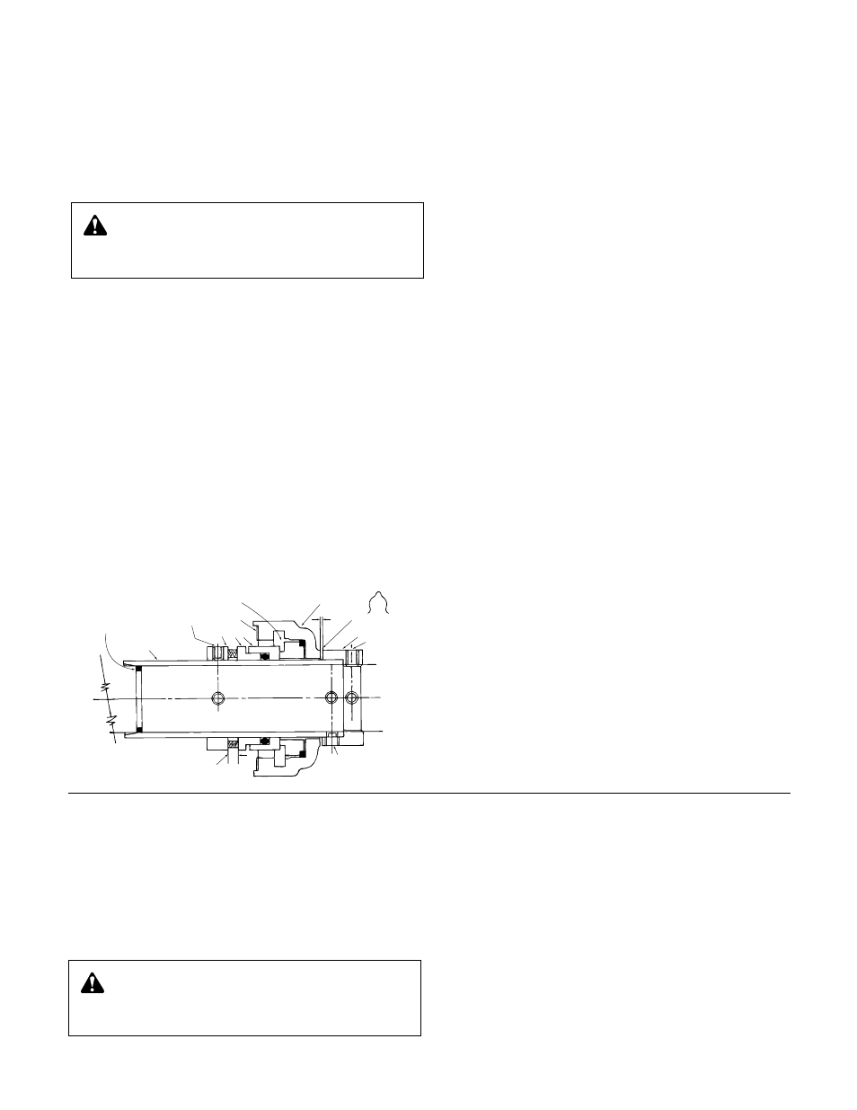
“O” RING*
SHAFT SLEEVE
SEAL COLLAR
SET SCREWS
ROTATING
SEAL MEMBERS
GASKET
SEAL CARBON
SEAL HOUSING
1
/
16
"
REF.
ASSEMBLY AID
DRIVE COLLAR
DRIVE COLLAR
SET SCREWS,
CUP POINT
PUMP SHAFT
COMPRESSION TO
1
/
4
"
*NOTE: On earlier models this groove is cut into the shaft sleeve.
SHAFT SLEEVE
SET SCREWS,
DOG POINT
SERVICE INSTRUCTIONS FOR PUMPS WITH A DOUBLE FLUSH MECHANICAL SEAL (VSC-D, VSCS-D)
(See special instructions for pumps 10 x 12 x 17, 12 x 14 x 12
1
/
2
, 12 x 14 x 17
1
/
2
and 8 x 10 x 17)
TO REPLACE THE SEAL OR SHAFT SLEEVE:
4. Remove bearing cover and release bearing cam lock.
5. Remove bearing housing capscrews. Pull housing and
bearing from shaft using capscrews in jackscrew holes.
6. Remove flush tube and capscrews from seal housing.
7. Remove outer two screws in shaft sleeve drive collar.
8. Remove stuffing box bracket capscrews and pull entire
stuffing box assembly from the volute coverplate.
9. Remove the seal cap and seal assembly from the stuffing
box.
10. If replacing the shaft sleeve, remove the sleeve and
replace. Inspect all parts to be re-used and replace if dam-
aged.
11. Lubricate stationary O-ring with silicone grease or soapy
water. DO NOT USE PETROLEUM LUBRICANT! Insert
O-ring toward impeller. Place one seal carbon into the bot-
tom of the stuffing box and carefully install in position.
12. Lubricate the O-rings of the rotating seal member and
position on sleeve against the seal carbon.
WARNING: Excessive Pressure Hazard
Make certain internal pressure is relieved before con-
tinuing. Failure to follow these instructions could result in
serious personal injury or death, or property damage.
SERVICE INSTRUCTIONS FOR PUMPS WITH A SINGLE FLUSH MECHANICAL SEAL (VSC-S, VSCS-S)
(See special instructions for pumps 10 x 12 x 17, 12 x 14 x 12
1
/
2
, 12 x 14 x 17
1
/
2
and 8 x 10 x 17)
TO REPLACE THE SEALS OR SHAFT SLEEVES:
4. Remove bearing cover and release bearing cam lock.
5. Remove bearing housing capscrews. Pull housing and
bearing from the pump shaft using capscrews in jack-
screw holes.
6. Remove flushing tube and capscrews from seal housing.
7. Remove outer two set screws in shaft sleeve drive collar.
Loosen two inner set screws one turn.
8. Remove the drive collar, seal housing, rotating seal assem-
bly and sleeve.
9. To assemble the pump, clean shaft sleeve and pump shaft.
Replace shaft sleeve if pitted or scored. If replacing the
seal, remove shaft O-ring and replace (included in seal kit).
10. Lubricate O-ring on stationary seal seat (carbon) with sili-
cone grease or soapy water. DO NOT USE PETROLEUM
LUBRICANT! Position in seal housing.
11. Place shaft sleeve in drive collar and tighten the two dog
point set screws in holes provided.
12. Set shaft sleeve and drive collar assembly on end and
place assembly aid spacer around the shaft sleeve.
Position against drive collar.
13. Place seal housing with carbon over the end of the sleeve
against assembly aid spacer.
14. Lubricate O-ring in rotating seal assembly with silicone
grease or soapy water. DO NOT USE PETROLEUM
LUBRICANT! Slip rotating seal assembly on the end of the
sleeve and place against carbon.
15. Compress rotating seal assembly to a
1
/
4
" space between
the seal parts that house the compression springs. Tighten
set screws.
16. Apply anti-seize compound only to the area of the shaft
that will be under the sleeve. Place seal housing gasket in
position and slide complete assembly over pump shaft.
IMPORTANT! When working on the seal on the non-
coupler end, it is necessary to force the pump shaft back
from the coupler end as far as possible and to hold it in
this position while installing and locking the bearing to the
shaft. Also, when replacing both seals, the seal on the
non-coupler end of the pump should be installed first.
17. Install the bearing housings. Clean and regrease the bear-
ings and insert into bearing housings. Push the pump shaft
back from the motor end as far as possible, using a lever if
necessary. Hold the shaft in this position. On the outboard
bearing tap inner race until it is properly positioned against
the shaft shoulder. Install and lock the cam lock into posi-
tion. If the shaft and bearing are properly positioned, the
cam lock set screw will fall in the center of the shaft under-
cut. Release the shaft. Install the outboard bearing cap.
Install the inboard bearing by tapping the inner race until it
contacts the shaft shoulder, lock the bearing in place with
the cam lock. Install the inboard bearing cap.
18. Push on the drive collar until the seal housing is against
the stuffing box bracket, bolt into place.
19. Tighten down collar set screws in undercut of shaft.
Remove assembly aid spacer and connect flush tubing to
seal housing.
20. Replace drain plug.
21. Install coupler and align, following the instructions located in
the section titled “Coupler Alignment.”
22. Install coupler guard. Refer to separate instructions titled
“Hex Coupler Guard Removal/Installation.”
23. Open isolation valves and check pump for leaks. If not
leaking, return pump to service.
WARNING: Excessive Pressure Hazard
Make certain internal pressure is relieved before con-
tinuing. Failure to follow these instructions could result in
serious personal injury or death, or property damage.
9