Installation, Leveling, Grouting – Bell & Gossett P81630F Series VSCS Base Mounted Centrifugal Pumps User Manual
Page 4: Rotation, Coupler alignment
4
INSTALLATION
This pump is built to provide years of service if installed properly
and attached to a suitable foundation. A base of concrete weigh-
ing 2
1
/
2
times the weight of the pump is recommended. (Check
the shipping ticket for pump weight.)
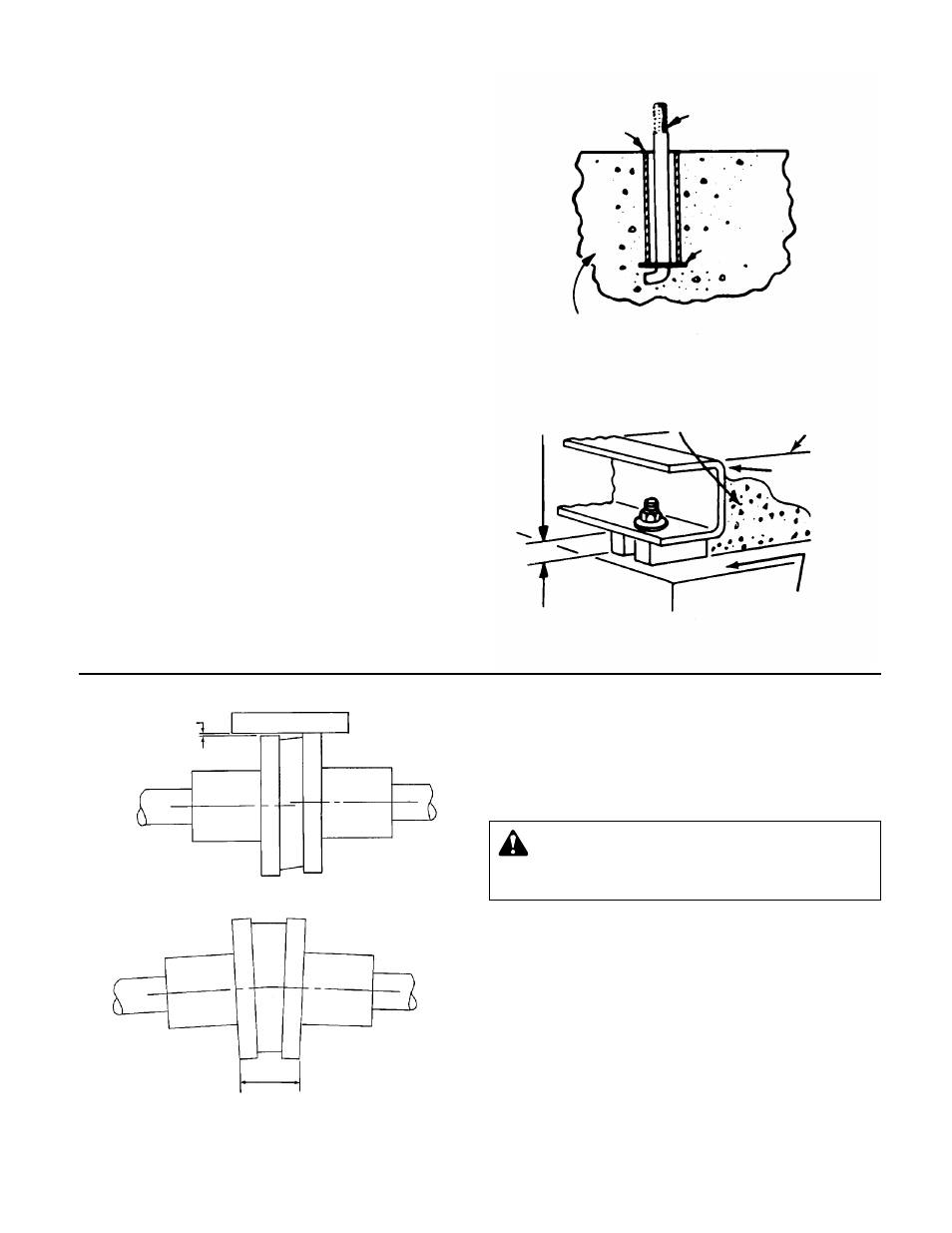
If possible, tie the concrete pad in with the finished floor. Use
foundation bolts and larger pipe-sleeves to give room for final
bolt location. (See Figure 6A.)
LEVELING
Place the pump on its concrete foundation supporting it with
steel wedges or shims totaling 1" in thickness. These wedges
or shims should be put on both sides of each anchor-bolt to
provide a means of leveling the base. (See Figure 6B.)
It is very important that the pump-base be set level to avoid any
mechanical difficulties with the motor or pump. This pump was
properly aligned (if furnished with a motor) at the factory. How-
ever, since all pump bases are flexible they may spring and twist
during shipment. Don’t pipe the pump until it is realigned. After
piping is completed and after the pump is grouted-in and bolted-
down, align it again. It may be necessary to re-adjust the align-
ment from time to time while the unit and foundation are new.
GROUTING
After the pump has been leveled, securely bolted to the floor,
and properly aligned, a good grade of non-shrinking grout
should be poured inside the pump base. To hold wedges or
shims in place, allow the grout to flow around them.
ROTATION
The VSC & VSCS pump is available in both right- and left-hand
rotation. An arrow cast into the pump body shows the direction
of rotation.
COUPLER ALIGNMENT
All alignment should be done by moving or shimming the motor
only. Adjustments in one direction may alter alignment in another.
Therefore, check alignment in all directions after a correction is
made. Black rubber inserts have different horsepower load
ratings than orange Hytrel sleeves. They should not be
interchanged.
STANDARD SLEEVE TYPE COUPLER
WITH BLACK RUBBER INSERT
Before aligning the coupler, make sure there is about
1
/
8
" end
clearance between the sleeve and the two coupler halves.
1. Check angular misalignment using a micrometer or caliper.
Measure from the outside of one flange to the outside of the
opposite flange at four points 90° apart. DO NOT ROTATE
COUPLER. Misalignment up to
1
/
64
" per inch of coupler
radius is permissible.
2. At four points 90° apart (DO NOT ROTATE COUPLER), mea-
sure the parallel coupler misalignment by laying a straight
edge across one coupler half and measuring the gap
between the straight edge and opposite coupler half. Up to a
1
/
64
" gap is permissible.
PIPE
SLEEVE
FOUNDATION
BOLT
BUILT-UP
CONCRETE FOUNDATION
GROUT ONLY TO
TOP OF BASE RAIL.
PUMP
BASE RAIL
APPROX.
1" GAP
CONCRETE
FOUNDATION
LEVELING OF PUMP BASE
ON CONCRETE FOUNDATION.
GROUT
FIGURE 6A
WASHER
FIGURE 6B
ALLOW 1" FOR SHIMS.
PLACE ON BOTH SIDES
OF ANCHOR BOLTS.
NOTE:
TO KEEP SHIMS IN
PLACE ALLOW GROUT
TO FLOW AROUND
HOLD DOWN LUGS.
WARNING: Unexpected Startup Hazard
Disconnect and lockout power before servicing.
Failure to follow these instructions could result in serious
personal injury or death, or property damage.
ANGULAR ALIGNMENT CHECK
AMOUNT OF
PARALLEL
MISALIGNMENT
STRAIGHT EDGE
PARALLEL ALIGNMENT CHECK
DISTANCES ACROSS
COUPLER FLANGES
SHOULD BE EQUAL
(CHECK 4 PLACES)