Bell & Gossett P81630F Series VSCS Base Mounted Centrifugal Pumps User Manual
Page 8
8
TO REPLACE THE SEALS:
4. Remove the bearing cover capscrews. To release the bear-
ing cam lock, loosen the allen set screw and tap the cam
lock counter-clockwise with a drift pin.
5. Remove two capscrews and loosen the remaining cap-
screws that hold the bearing housing to the volute coverplate.
Remove the bearing housing by placing two capscrews in
the jackscrew holes provided.
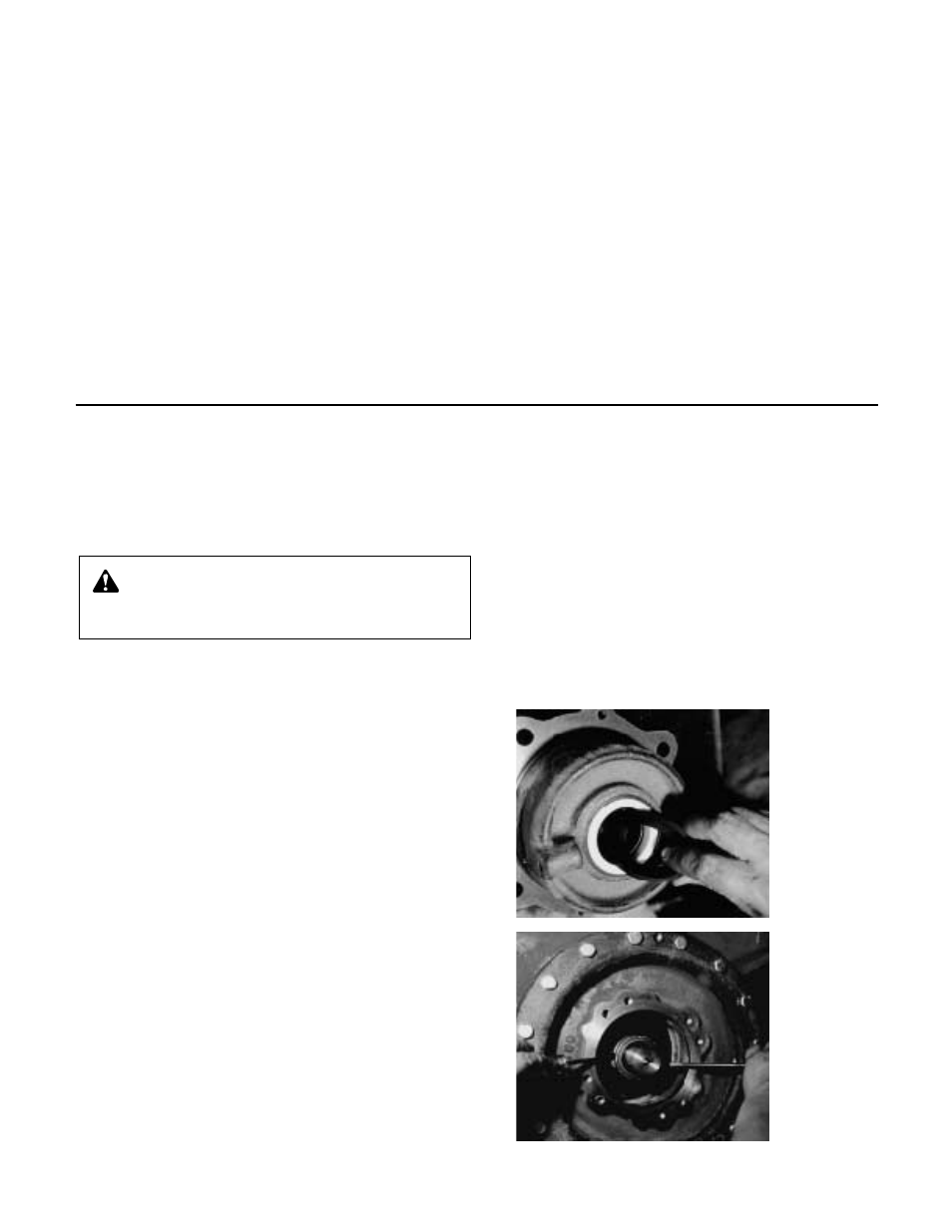
6. Remove the bearing from the bearing housing by gently
tapping the bearing’s inner race. NOTE: If the water slinger
has fallen into the bearing housing, be sure to remove and
replace with the one provided (see Figure 1). Take care to
avoid damage to the ceramic seal insert.
7. Remove the ceramic insert from housing by tapping from
the rear.
8. Using 2 screwdrivers, pull the rotating seal assembly from
the pump shaft (see Figure 2). Clean and inspect the shaft
and bearing housing for damage, replace if required.
IMPORTANT: When working on the seal on the non-
coupler end, it is necessary to force the pump shaft back
from the coupler end as far as possible and to hold it in
this position while installing and locking the bearing to the
shaft. Also, when replacing both seals, the seal on the
non-coupler end of the pump should be installed first.
9. Lubricate the seal assemblies and insert cups with soapy
water, and then place the rotating seal assemblies on the
shaft and the ceramic inserts and cups into each of the
bearing housings, make certain inserts bottom against
bores. Install the bearing housing gaskets and the bearing
housings on the pump.
10. Slide the water slingers on the shaft and over the shoulder
so as not to interfere with the bearings. Clean and re-
grease bearings and insert into bearing housings. Push the
pump shaft back from the motor end as far as possible,
using a lever if necessary. Hold the shaft in this position.
Tap on the outboard bearing inner race until it is properly
positioned against the shaft shoulder. Install and lock the
cam lock into position. If the shaft and bearing are properly
positioned, the cam lock set screw will fall in the center of
the shaft undercut. Release the shaft. Install the outboard
bearing cap. Install the inboard bearing by tapping the
inner race until it contacts the shaft shoulder, lock the bear-
ing in place with the cam lock. Install the inboard bearing cap.
11. Replace drain plug.
12. Install coupler and align, following the instructions located in
the “Coupler Alignment” section.
13. Install coupler guard. Refer to separate instructions titled
“Hex Coupler Guard Removal/Installation.”
14. Open isolation valves and check pump for leaks. If not
leaking, return pump to service.
SERVICE INSTRUCTIONS FOR PUMPS WITH A STANDARD MECHANICAL SEAL (VSC-VSCS)
WARNING: Excessive Pressure Hazard
Make certain internal pressure is relieved before con-
tinuing. Failure to follow these instructions could result in
serious personal injury or death, or property damage.
FIGURE 1
FIGURE 2
1. Remove coupler guard and coupler.
2. Remove both bearing caps and bearing lock nuts.
3. Remove both bearing housings together with bearing.
4. Remove outboard cover plate.
5. Remove shaft and impeller assembly.
6. Remove impeller nut and pull (press fitted) impeller from
shaft. Observe direction that vane tips are pointing. Turn
impeller end for end (180°) and press back onto shaft.The
vane tips should be pointing in the opposite direction.
7. Remove volute from base. Remove inboard cover plate
from volute.*
8. Reassemble cover plate, which was removed from out-
board side, by placing on same side of volute. Turn volute
end for end (180°) and mount back on base. The cover
plate that was located on the outboard side of the pump,
should now be on the inboard (motor) side of the pump.
9. Insert shaft assembly, with reversed impeller, back into
pump casing and reassemble second cover plate (now
outboard) to volute.
10. Reassemble seals, bearing housings, bearing and bearing
caps. (Bearings and housings are identical side to side.)
11. Reassemble coupler and reattach guard.
In summary, the impeller, volute and cover plates should all
have been reversed end for end. The orientation of the remain-
ing parts should not have changed.
*It is important to remember that in the order to keep the water pas-
sages open, the cover plates must be reassembled to the same side
of the volute from which they were removed. In effect, they should be
rotated along with the volute. In fact, the inboard cover plate does not
need to be removed, if the complete pump end is reassembled before
being mounted on the base.
INSTRUCTIONS FOR CHANGING DIRECTION OF ROTATION FOR VSC AND VSCS PUMPS