Bell & Gossett AC8584D Series HSCS Base Mounted Centrifugal Pumps User Manual
Page 27
2
7
56;,! Inboard bearing cover (3-018-3) is approximately
1/4 inch less in width than the outboard bearing cover
(3-018-4). This is the only dimensional difference.
13. Press heated bearing (3-026-2) on shaft against snap ring
or thrust washer, Install locknut (3-516-4) and lockwasher
(3-517-4) on outboard end. Make certain the locknut is
secured and then bend over tab on lockwasher.
7<47:>0;/.9,(:,3<)90*(;065
14. Cool bearings at room temperature and coat with 2 or 3
ounces of a recommended grease. Refer to page 26 for
installation of oil lubricated parts.
7<47:>0;/6033<)90*(;065
Refer to page 26 for installation of oil lubricated parts.
15. Assemble oil seals (3-177-9) in each bearing housing.
Refer to
56;, under number 11 for direction of oil seal.
16. Slide bearing housings (3-025-2) over bearings (3-026-2).
17. Assemble bearing cover to bearing housing with two cap
screws (3-904-9).
18. Replace pump coupling half and key (3-911-2).
19. Assemble rotating element in lower half casing (2-001-8).
Correctly locate casing ring pins (3-943-9) in casing main
joint slot.
56;,! Sliding inboard bearing housing toward coupling
prior to assembling rotating element in casing will ease
assembly.
20. Bolt outboard bearing housing in place. Be sure that both
housings are seated in lower half casing.
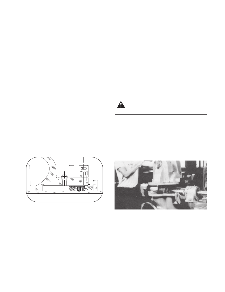
21. Bolt inboard bearing housing in place. If seal is a John
Crane Type 8, set seal to dimension shown in Figure 22
and tighten set screws.
22. Clean the gasket surfaces of the casing. Apply Scotch
3M-77 spray adhesive or equivalent to the lower half of
the casing.
23. Within one minute of spraying, set the gaskets (2-123-5,
-6) in place on the lower half casing, align the holes in the
gaskets with the holes in the casing and press the gas-
kets firmly against the lower half casing face in the area
coated by the adhesive.
24. Lower upper half casing (2-001-7) into place (See Figure
23) and locate using the taper dowels (2-916-9) and
install casing main joint bolts (2-904-9). The casing joint
bolts should be tightened to the following torques: 300ft-
lb minimum for .75"-10 Ferry Cap Counterbore screws
(Grade 8), 400ft-lb minimum for 1.0"-8 Ferry Cap
Counterbore screws (Grade 8). Bolt torquing pattern is
shown in Figure 10. Before tightening bolt, be sure taper
dowels are seated properly in reamed holes.
56;,! Torque valves are essential in obtaining proper
gasket compression so no leakage can occur at main
joint.
25. Slide deflectors (3-136-9) toward bearing covers. Allow
rotating clearance of approximately 1/16".
26. Rotate shaft by hand to assure that it turns smoothly and
is free from rubbing and binding.
27. Bolt glands (3-014-2) to casing with gland bolts (3-904-9).
28. Assemble seal water lines (0-901-0, 0-950-0, 0-952-0) to
stuffing box and casing. Seal water lines go to outside
holes (See Figure19).
29. Check coupling alignment and redowel if necessary.
*(<;065!
Double check rotation of pump before installing the
upper half casing. (Refer to Figure 9.)
-0.<9,¶36>,9*(:05.*6=,965;636>,9/(3-
-0.<9,¶4,*/(50*(3:,(336*(;05.+04,5:065