Reassembly – Goulds Pumps CV 3171 - IOM User Manual
Page 41
CV 3171 IOM 05/11
41
REASSEMBLY
Refer to Table 7 for torque values while reassembling pump.
Table 7
BOLT TORQUE TABLE
Location
Lubricated Threads
Dry Threads
Casing Bolts (370)
30 FT-LBS (40 Nm)
45 FT-LBS (60 Nm)
Column Pipe to
Adapter Bolts (370G)
20 FT-LBS (27 Nm)
30 FT-LBS (40 Nm)
Steady Bearing
Bolts (372B)
20 FT-LBS (27 Nm)
30 FT-LBS (40 Nm)
Column Pipe to
Motor Mount (370M)
20 FT-LBS (27 Nm)
30 FT-LBS (40 Nm)
Motor Mount to
Support Plate (370L)
30 FT-LBS (40 Nm)
45 FT-LBS (60 Nm)
Motor to
Motor Mount (371)
20 FT-LBS (27 Nm)
30 FT-LBS (40 Nm)
Strainer to Case (317N)
20 FT-LBS (27 Nm)
30 FT-LBS (40 Nm)
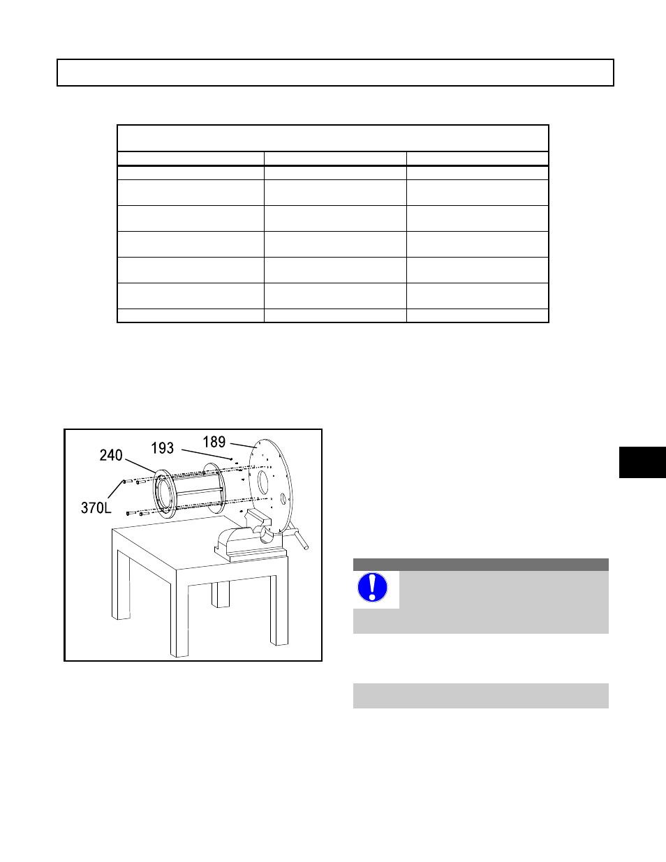
ASSEMBLY OF MOTOR SUPPORT,
HEAD COLUMN, AND SUPPORT PLATE
1. If motor support disassembled, attach motor
support (240) to support plate (189) with bolts
(370L) (Figure 33).
2. Attach head column (192) to motor support with
bolts (370M). Vent holes should be closer to the
motor support.
OPTIONAL WITH STUFFING BOX
DESIGN
Refer to Figure 48, Appendix II.
1. Attach stuffing box (221) to support plate (189)
with bolts (370L).
2. Attach motor support (240) to stuffing box with
bolts (370J).
3. Attach head column (192) to stuffing box with
bolts (370M). Vent holes should be closer to the
motor support.
ASSEMBLY OF ROTATING ELEMENT
CAUTION
Shafts can be damaged by improper
handling. Extreme care should be taken
at all times. It is recommended that
shafts over 9 feet long be handled by two people
at all times to prevent possible bending.
1. Install retaining ring (369A) on shaft (122)
(Figure 34).
NOTE: S/ST groups do not use the 369A
retaining ring.
2. Install thrust bearing (112) on shaft (122).
Figure 33
6