No pit cover, Impeller clearance setting, Motor installation and coupling alignment – Goulds Pumps CV 3171 - IOM User Manual
Page 17
CV 3171 IOM 05/11
17
NO PIT COVER
Standard Support Plates
1. Carefully lower the pump and support plate onto
the foundation bolts.
2. Level the support plate in all directions using
shims and wedges.
3. Hand tighten the anchor bolts, check the level
and re-shim if necessary.
4. Tighten all anchor bolts in a star pattern to avoid
distorting the support plate.
5. Assure that the support plate is level.
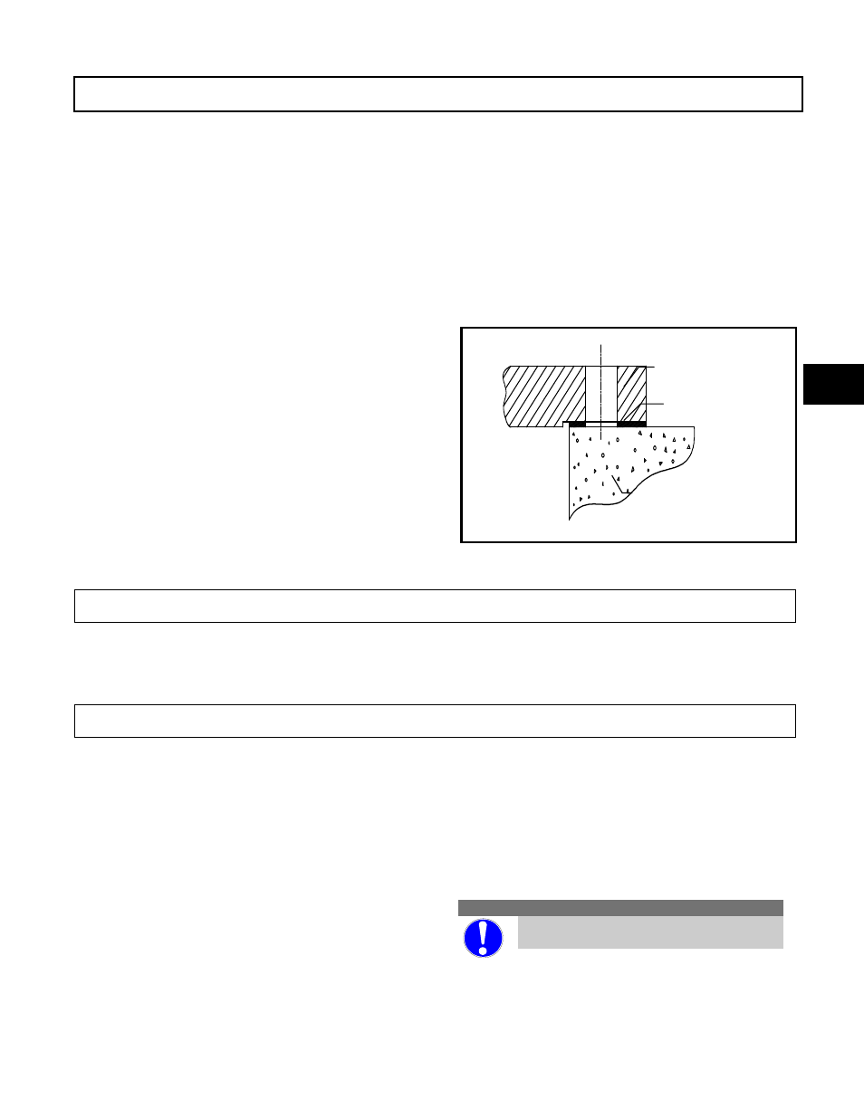
Vapor Proof Option
The support plate/foundation fit is a gasketed fit.
The support plate should be bolted to a metal sole
plate with a machined surface to insure an airtight
seal. Refer to Figure 6 for standard layout. A gasket
is supplied for installation between the two flanges
to insure an airtight fit.
Tank Flange Support Plates
1. Mating flange on the tank must be level. Very
minor adjustments can be made with gasket
material between the two flanges.
2. Install all bolts finger tight.
3. Tighten all bolts in a star pattern to avoid any
distortion of the support plate.
IMPELLER CLEARANCE SETTING
Adjust the impeller clearance setting. This
procedure is easiest to perform without the motor
and coupling installed. See Section 5, “Impeller
Clearance Setting” for proper procedure.
MOTOR INSTALLATION AND COUPLING ALIGNMENT
The Model CV3171 is designed for use with NEMA
Vertical C-face motors. P-Base motor adapters and
IEC motor adapters are available as options.
Installation
1. Install both coupling halves prior to mounting
the motor. Refer to the coupling manufacturers
instructions.
2. Using the lifting lugs on the motor, carefully
lower the motor onto the pump and align the
bolt holes.
3. Install motor bolts and finger tight.
4. Before the coupling is connected, the motor
must be wired and the direction of rotation
checked. A rotation arrow is located on the
motor support. Correct rotation for the pump is
CW looking down from the driver at the
impeller.
Checking Rotation
CAUTION
Serious damage may result if pump is
run in the wrong direction.
Figure 6
3
FOUNDATION
GASKET
189