U-ds40 smart table • assembly instructions, Fb l o – Martin Universal Design U-DS40 SMART TABLE User Manual
Page 2
03/2009- RPI
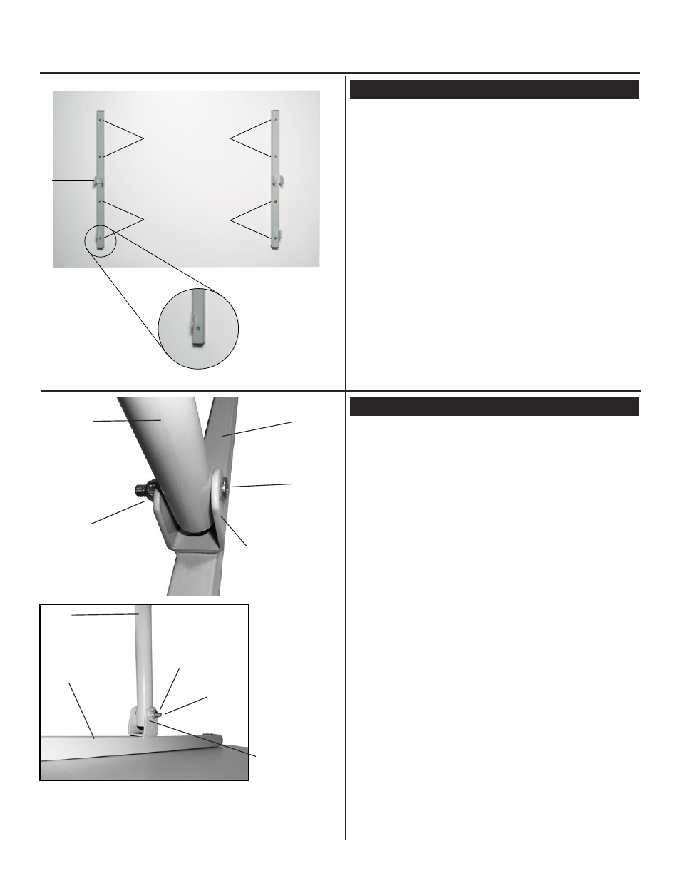
STEP 1] Attach Base supports to Top
FIG 1
Pg. 2
U-DS40 SMART TABLE • Assembly Instructions
IMPORTANT:
ASSEMBLE TABLE ON FLAT CARPETED
SURFACE TO PROTECT TOP FROM MARRING
Make sure the base
supports are
positioned so that the
tab is on the outer
side of the base
support.
See image to the left
FIG 1b.
STEP 2] Attach Upper Legs
Begin by taking your table top (part A) and lay it face
down onto your flat carpeted work surface
(holes facing up). Take [2 each] Base Supports
(part B) and position them so that they line up with the
holes in the top and metal tab is positioned on the outer
side of the base support.
See FIG 1b.
Using [4 each] 6x25mm Screws (part K) per base
support. Secure by tightening these screws to secure
base support to top. Repeat with second base support
(part B).
To attach the upper legs (part F) to the base supports
(part B), line up the hole found in the upper leg with the
welded brace found on the base support. Line up the
holes, insert a 6x40mm Allen Bolt through the welded
brace then through the upper leg and then through
the other side of the welded brace add a nut (part O).
Tighten to secure.
See FIG 2 & 2b.
Repeat with second upper leg.
FIG 2
F
B
L
O
welded brace
welded brace
F
B
L
O
FIG 2b
K
K
K
K
A
B
B
FIG 1b