頁面 6 – MIPRO ACT-515 Single-Channel True Diversity Receiver User Manual
Page 6
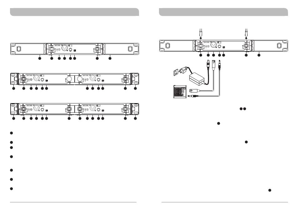
Antenna Installation:
Install 2 separate antennas on the antenna sockets on the rear panel.
illustrated in Figure 1.
Connecting the power supply:
!
Plug DC plug into the DC-input jack and the power cord, into a power outlet. ACT-
515T/ACT-515BT receiver has two DC input jacks. Either is acceptable for
connecting.
Audio Output Connection:
Level Switch Setting Position for Unbalanced Output :
When connecting from receiver's unbalanced output to the “LINE-IN” jack of a mixer
or amplifier or “Electric Guitar”, switch the Level Switch to “LINE” position. Low
sensitivity may occur if switch to the wrong level position. When connecting from
receiver's unbalanced output to the “MIC IN” jack of a mixer or amplifier; switch
the Level Switch to “MIC” position. Louder or quieter volume of microphone may
occur if switch to the wrong level position. When using electric guitar, don't use
“MIC” position as it may have generated insufficient level.
Connection Method of Unbalanced Output:
When receiver and mixer/amplifier is under short distance. Or the connectors of
receiver/mixer/amplifier are “PHONE” types. Using audio output cable attached with
“PHONE PLUG” type, connect one end from the unbalanced output jack , of the
receiver, and the other end to the “LINE-IN” input jack of the mixer/amplifier, as
shown in Figure 1.
!
!
!
Receiver Installation
(Figure 1)
23
21
24
25
20
22
20
23
24
25
21
26
BALANCED OUT
DC IN
(12~15V)
OUTPUT
LEVEL
LINE
MIC
3: COLD
1: GND
-
+
2: HOT
3
2
1
Rear Antenna 'B' Input Connector: The 'B' antenna can be installed directly to
this antenna connector which also provides power to an optional antenna booster.
DC Input Jack: Accepts +12V DC (center pin is positive and sleeve is ground).
Balanced Audio Output Jack: XLR type connector provides balanced audio
output signal from this jack to the mixer. Selectable: Mic or Line.
Unbalanced Audio Output Jack: 6.3mm (1/4”) phone-jack type connector
provides unbalanced audio output signal from this jack to the mixer. Selectable:
Mic or Line.
Mic/Line Switch: MIC level is microphone output level (0dB). LINE level is
auxiliary output.
Rear Antenna 'A' Input Connector: The 'A’ antenna can be installed directly to
this antenna connector which also provides power to an optional antenna booster.
Rack-Mount Brackets: Fits into a standard 19-inch rack case.
MIPRO FBC-71 rear-to-front cables can be installed for front antenna placement to
improve reception quality.
Receiver Controls and Indicators
Rear Panel
21
22
23
24
25
26
20
BALANCED OUT
DC IN
(12~15V)
OUTPUT
LEVEL
LINE
MIC
3: COLD
1: GND
-
+
2: HOT
3
2
1
BALANCED OUT
DC IN
(12~15V)
OUTPUT
LEVEL
LINE
MIC
3: COLD
1: GND
-
+
2: HOT
3
2
1
LEVEL
LINE
MIC
OUTPUT
BALANCED OUT
DC IN
(12~15V)
3: COLD
1: GND
-
+
2: HOT
3
2
1
BALANCED OUT
DC IN
(12~15V)
OUTPUT
LEVEL
LINE
MIC
3: COLD
1: GND
-
+
2: HOT
3
2
1
LEVEL
LINE
MIC
OUTPUT
BALANCED OUT
DC IN
(12~15V)
3: COLD
1: GND
-
+
2: HOT
3
2
1
26
22
20
23
24
25
21
26
26
26
26
26
22
22
20
23
23
24
24
25
25
21
21
22
22
20
20
23
23
24
24
25
21
21
ACT-515T/ACT-515BT Dual Channel (Detachable 1/2 Wave Antenna ×2)
ACT-515T/ACT-515BT Dual Channel (Detachable 1/2 Wave Antenna ×4 Optional)
ACT-515/ACT-515B Single Channel
6
7
Diversity Wireless Systems
Diversity Wireless Systems