頁面 12 – MIPRO ACT-515 Single-Channel True Diversity Receiver User Manual
Page 12
General Tips for Improving System Performance
1. Since the installation of the antenna influences the operating efficiency of the
receiver, the most important rule is to minimize the distance as much as possible
between the receiving antenna and the microphone for the best reception and
performance.
2. Use MIPRO supplied antennas to ensure proper receiver sensitivity. The external DC
power supply should not fall under 12V, otherwise it would not work properly. If it is
over 15V, some components of the receiver will be damaged.
3. The antenna socket provides an 8V DC biased output. Therefore, shorting on the
antenna socket should be avoided. Temporary shorting on the antenna socket will
not affect system performance; however, continuous shorting on the antenna socket
will cause permanent system damage.
4. If extended reception distance is needed, installing a MIPRO AT-90W/AT-100
directional antenna kit, which includes internal boosters will increase the reception
distance.
5. Proper antenna distribution is vital to achieving ideal performance from multiple
wireless systems operating in the same venue. To greatly reduce antenna clutter in
multi-system installations, a MIPRO AD-707a/AD-708, UHF antenna divider system is
recommended. Each AD-707a/AD-708 supports up to four UHF diversity receivers to
operate from a single pair of antennas. When combined with an AT-70A/AT-70W
omni-directional extension antenna and an MPB-20 antenna booster or an AT-90W/
AT-100 wide-band directional antenna, the AD-707a/AD-708 antenna divider
provides optimal signal reception with minimal dropouts or interference.
6. MIPRO's factory preset Interference-free channels within the same channel group
are recommended to ensure optimum performance from multiple wireless systems
installed in the same venue. Use of preset Interference-free channels from different
channel groups may cause interference, thus is not recommended.
Notes:
Refer to actual product in the event of product discrepancy.
Frequency range and maximum deviation comply with the regulations of different
countries.
!
!
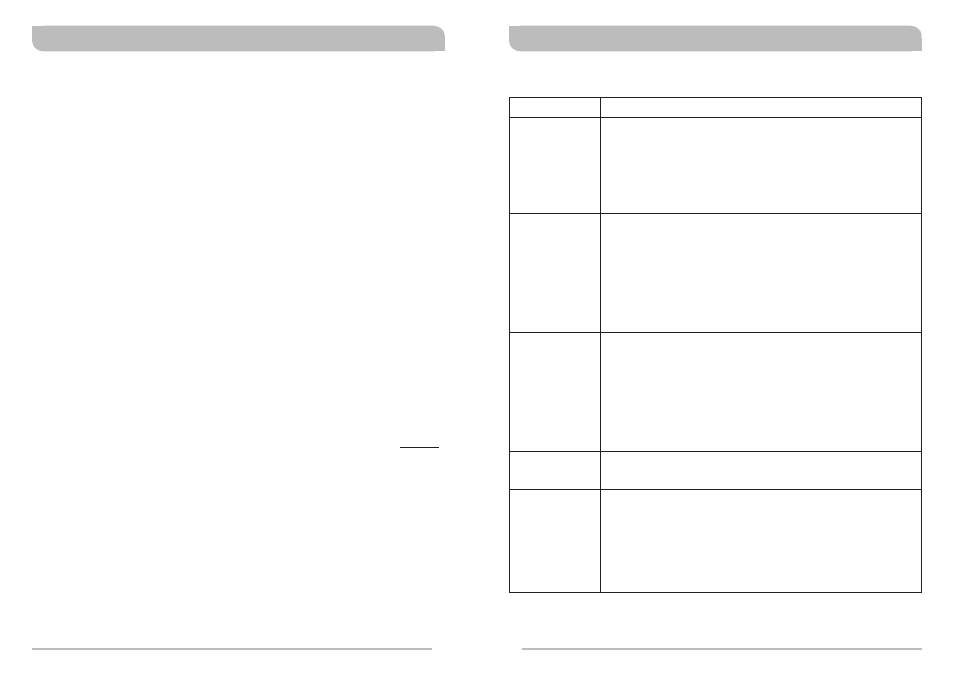
Troubleshooting
Symptom
Solutions
No Sound
! Power-on receiver & transmitter.
! Receiver is plugged into a power outlet and cable connected
to mixer/amplifier.
! Fresh batteries in transmitter and inserted with correct
polarity.
! Match receiver & transmitter frequency.
! Close proximity between the transmitter and receiver antenna.
! Line-of-sight path between the transmitter and receiver
antenna.
! Reposition the receiver and/or receiver antennas.
! Receiver antennas are connected.
! Elevate receiver antennas as high as possible.
! Keep hands off of the transmitter antenna.
! Close proximity between the transmitter and receiver antenna.
! Adjust antenna orientation.
! Reposition the receiver and/or receiver antennas.
! Receiver antennas are connected.
! Undamaged antennas.
! Fresh batteries in transmitter.
! Adjust for proper squelch level setting.
! Match receiver & transmitter frequency.
! Adjust for proper squelch level setting.
! Reduce transmitter gain, if set too high.
! Recommendation: set to 0dB (Mic Level).
! Reduce receiver output setting.
! Proper setting on mixer input gain or integrated amplifier mic
level control.
! Fresh batteries in transmitter.
Signal Drop-outs
Limited Range
No RF Signal
Distortion
18
19
Diversity Wireless Systems
Diversity Wireless Systems